Memory
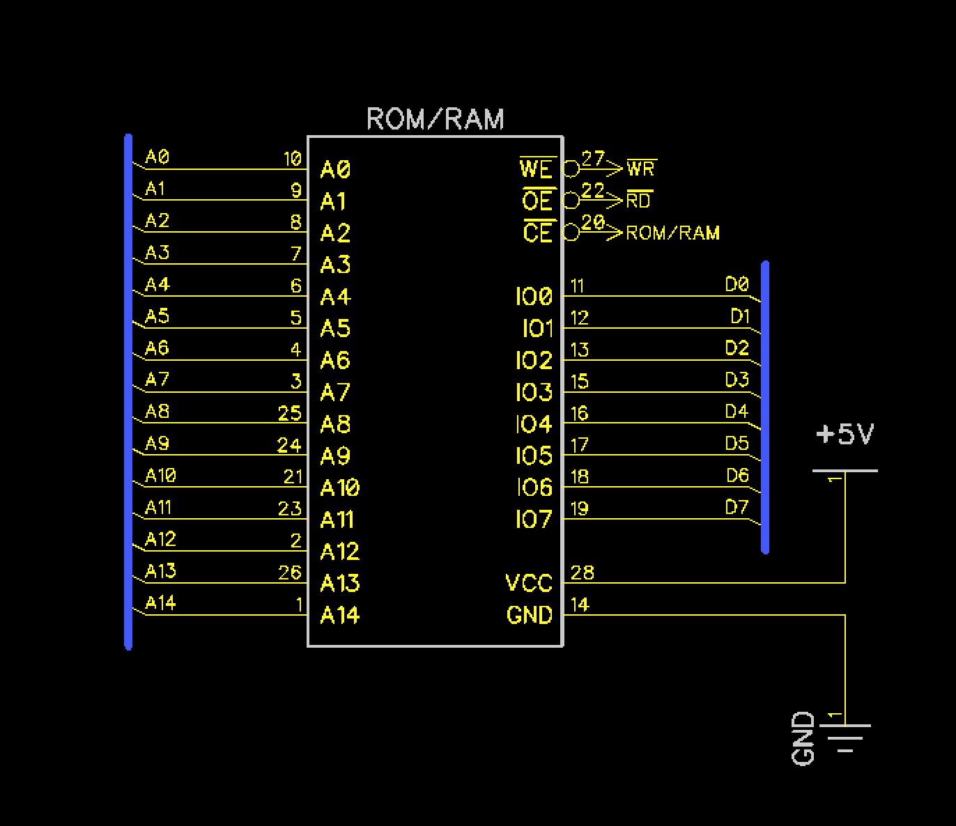
Circuit Diagram
Background
Dodo uses a 32KB SRAM for system memory and a 32KB EEPROM for system firmware. Both chips happen to have the exact same pinout and both are connected identically, therefore only one chip is shown above in the diagram.
Pin Descriptions
| Pin(s) | Discription |
|---|---|
| Address | A0 - A14 address lines. Note that the 65C02 has an additional address line because the 65C02 has 64KB total address space. A15 from the processor is connected to the glue logic. |
| Data | D0 - D7 data bus |
| WE | Write enable. Conneced to WR which is generated from the RW signal from the 65C02. See glue logic. |
| OE | Output enable (Read). Connected to RD which is also generated from the RW signal |
| CE | Chip enable. From the RAM this is connected to the RAM chip select. For ROM, it is connected to the ROM chip select. See glue logic. |
Components
| Component | Description | Image |
|---|---|---|
| AT28C256 | EEPROM | 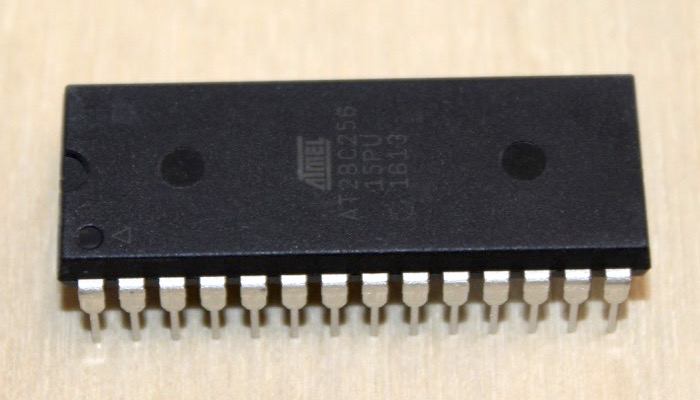 |
| AS6C62256A | SRAM | 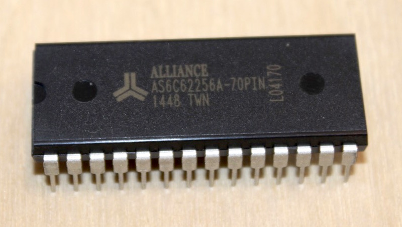 |
| IC Socket | Socket for the EEPROM | 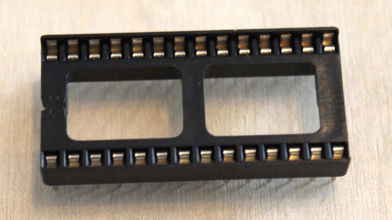 |