I/O
Circuit Diagram
Background
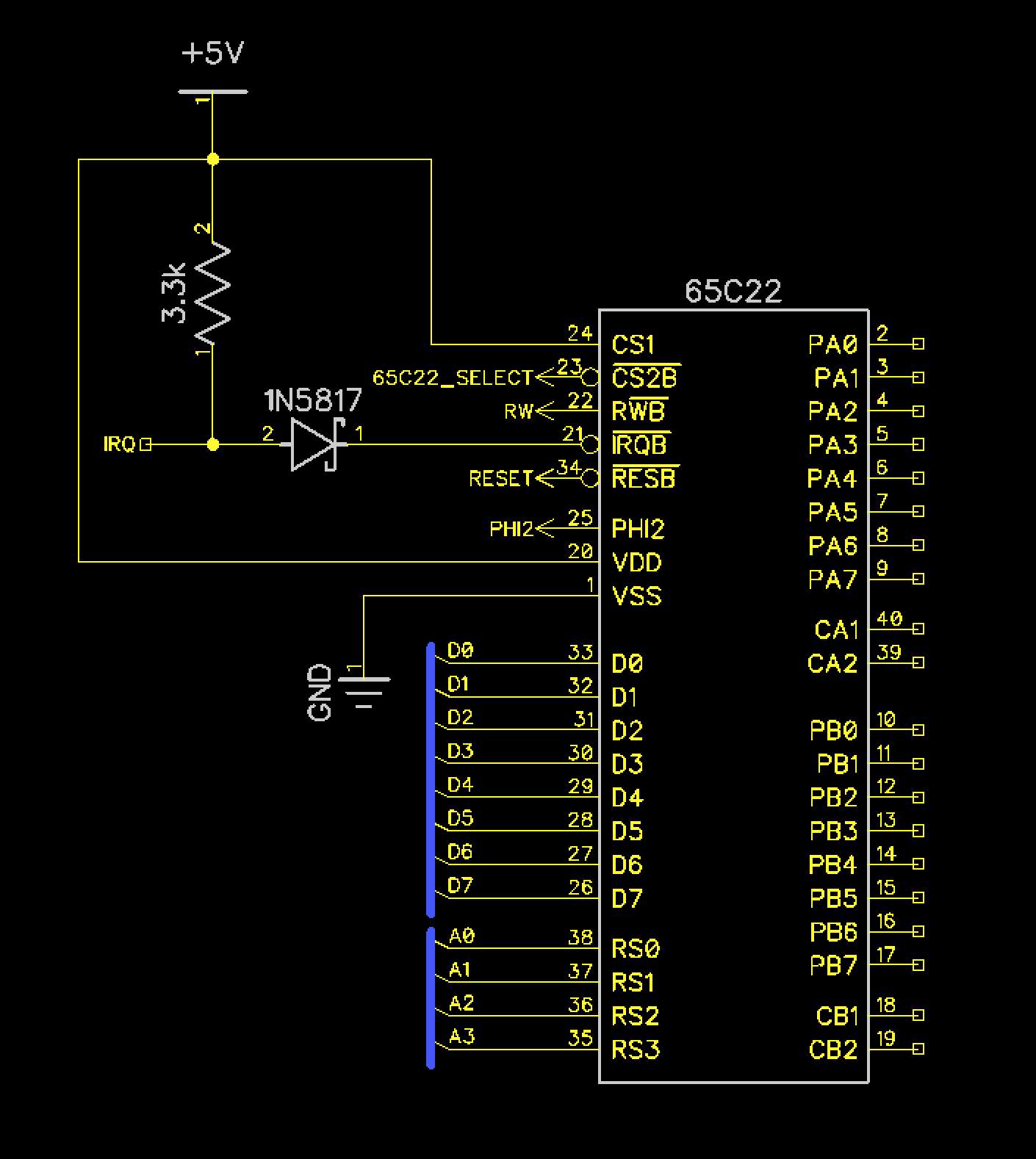
Dodo’s I/O functionality is powered by the 65C22S peripheral chip. The 65C22S has dual timers and dual 8-bit bidirectional I/O ports. Dodo takes advantage of nearly all of this functionality. The first timer is used to generate an interrupt every 50ms to pump the game loop to keep a consistent frame rate. The 2nd timer drives a free running shift register that is connected to the speaker for generating a single voice of square wave audio. Port A is connected to the buttons and Port B is used for connecting to the game cartridge over SPI.
Traditonally IRQ lines on the 6502 family of chips have been open drain outputs, which means that they all can be tied together. The 65C22S breaks this tradition, and the expectation is that the IRQ lines should be fed into an AND gate. In order to avoid adding another DIP chip to Dodo just for a single AND gate, a shottky diode is used as a gate.
In the diagram below all pins on the right of the IC are connected to the 50 pin header that goes to the I/O board.
Pin Descriptions
| Pin(s) | Discription |
|---|---|
| CS1 | Chip Select 1, tied high, not needed |
| CS2B | Chip Select 2, connected to the 65C22 select generated by the glue logic |
| RWB | Read/Write Connected to RW from the processor |
| IRQ | Connected to IRQ on processor via diode and pullup |
| RESB | Connected to the Reset line |
| PHI2 | Connected to the 1mhz oscillator |
| Data | D0 - D7 data bus |
| RSO - RS3 | Register address lines. Connected to A0 - A3. Chip select is generated based on the other address lines, least significan 4 bits determine register. |
| PA0 - PA7 | Port A |
| CA1, CA2 | Timer pins for port A |
| PB0 - PB7 | Port B |
| CB1, CB2 | Timer pins for port B |
Components
| Component | Description | Image |
|---|---|---|
| 65C22S | Peripheral Chip | 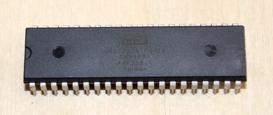 |
| 3.3k Resistor | IRQ Pullup | 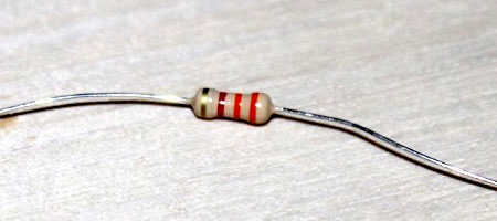 |
| Diode 1N5817 | Substitute for AND gate | 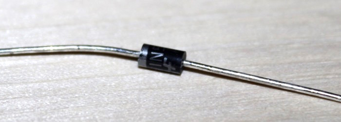 |
| 50 pin Male Header | Male Header to connect to I/O board |  |