Processor
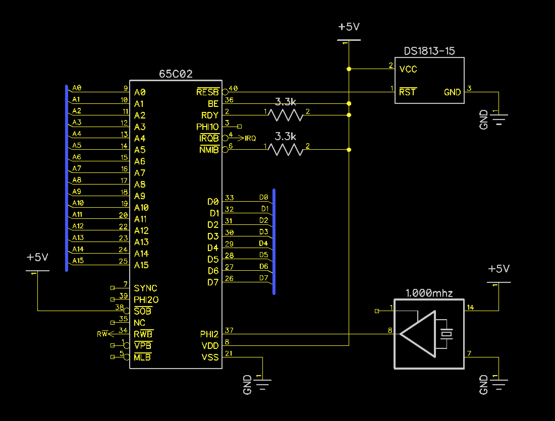
Circuit Diagram
Background
Dodo uses a WDC 65C02 processor which is still in production today. The original 6502 was NMOS, the 65C02 is CMOS and is more efficient. Addionally, the 65C02 fixes several issues that are found in the NMOS version. The processor Dodo uses is contained in a DIP-40 package.
Note that a number of pins are left disconnected as they are not needed for Dodo’s design. Also, certain pins are no longer recommended to be used according to the datasheet, such as PHI1O and PHI2O.
Pin Descriptions
| Pin(s) | Discription |
|---|---|
| Address | 16 Address lines (A0 - A15) designate the memory location that the processor is reading or writing. |
| Data | 8 Data Lines (D0 - D7) form the data bus |
| BE | Bus Enable. Unused by Dodo. Allows external circuitry to access bus |
| IRQ | Interrupt Request (Used by 65C22 and 65C51) |
| NMIB | Non-Maskable Interrupt. Unused by Dodo |
| MLB | Memory Lock. Unused by Dodo. Used by multiprocessor systems to wait for read-modify-write instructions to complete. |
| PHI2 | Clock Input, connected to 1mhz oscillator |
| PHI20 | Clock Output. Not recommended by WDC |
| PHI10 | Inverted Clock Output. Not recommended by WDC |
| RWB | RW pin. Connected to RW of other I/O chips and used to generate RD and WR signals for memory chips and display |
| RDY | Allows external halting of the processor. Unused by Dodo |
| RESB | Reset line which is tied to the reset circuit |
| SOB | Set Overflow. Magical pin that allows externally setting overflow bit in processor flags. Unused by Dodo. |
| SYNC | Signifies when processor fetching Opcode. Unused by Dodo. Could be used for single stepping instructions. |
| VPB | Signifies processor fetching the interrupt vectors. Unused by Dodo. |
Reset
A 65C02 starts by the RESB pin being held low for at least 2 clock cycles at which time it will then read the initialization vector (FFFC) and then jmp to the read location. Reset circuits that hold the pin low for a duration can be accomplished a number of ways, for example the Commodore 64 used a 555 timer circuit. Dodo uses the DS1813 which is an integrated reset package.
Note that the IRQ line also requires a 3.3k pullup resistor which is shown elsewhere.
Components
| Component | Description | Image |
|---|---|---|
| 65C02 | Processor | 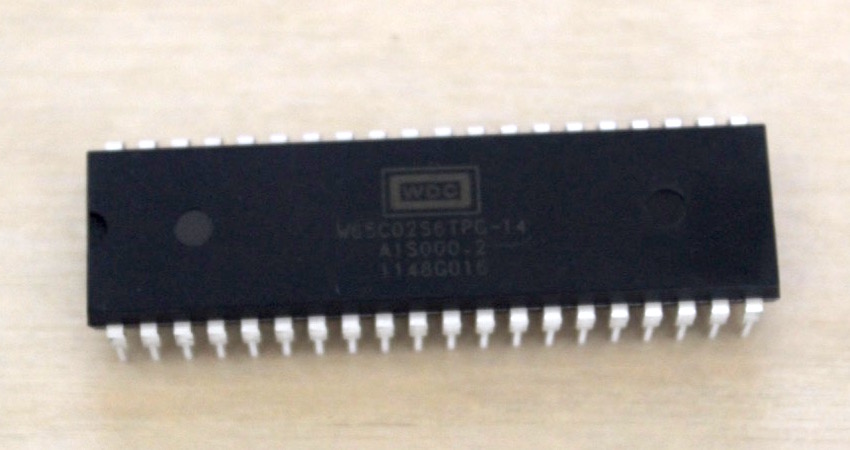 |
| 3.3k Resistors (2x) | Pullups | 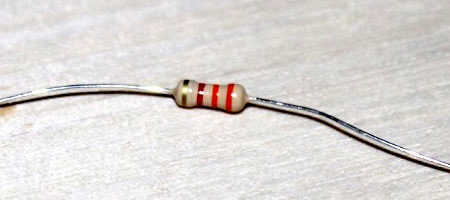 |
| 1.000mhz oscillator | Clocks the processor at 1mhz | 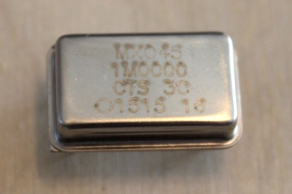 |
| DS1813 | Integrated reset logic |  |