RS-232
Circuit Diagram
65C51
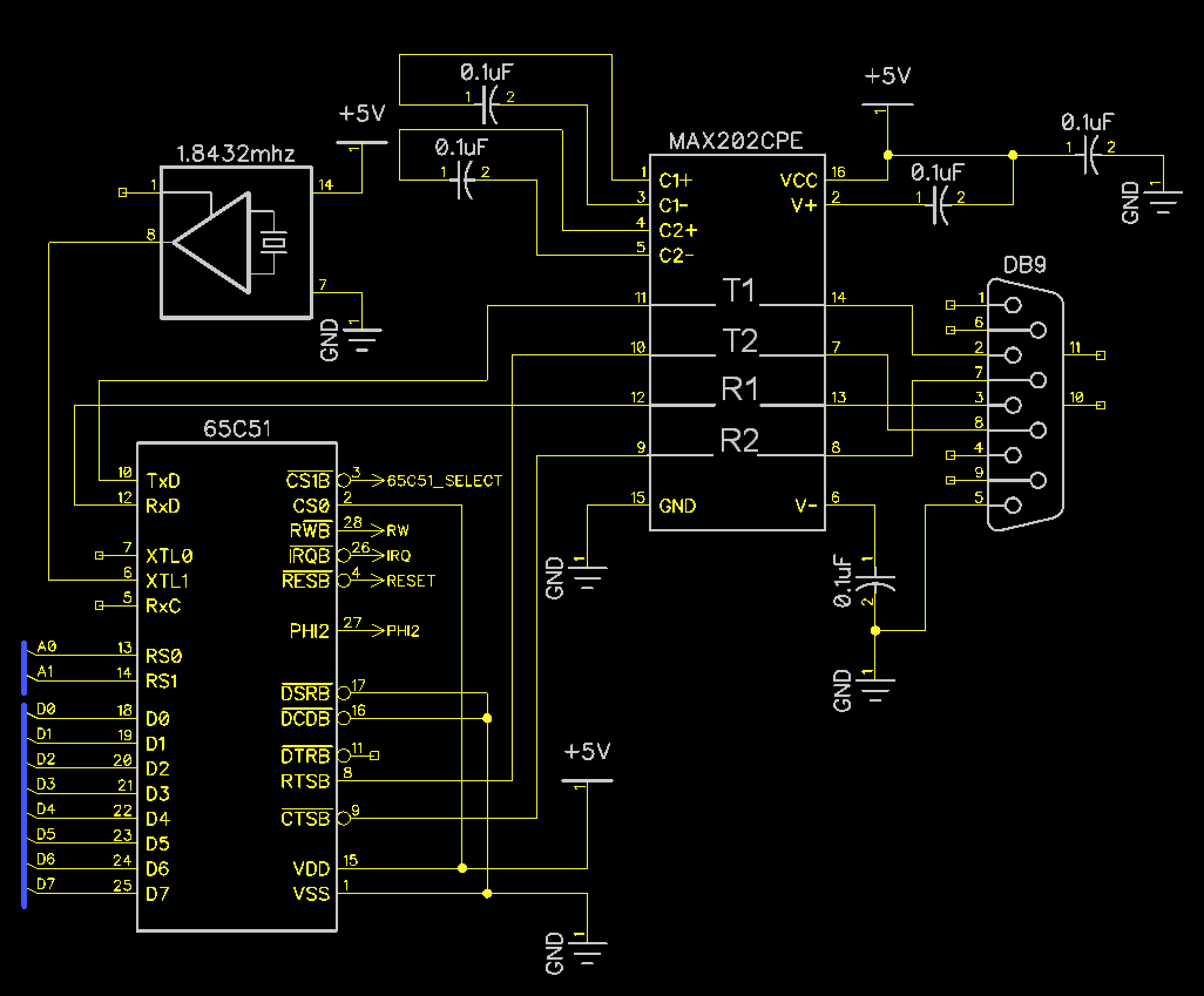
Dodo requires a connection to a host computer in order to flash games onto the cartridges and to update the system firmware on the EEPROM. That connection is RS-232. RS-232 connectivity is provided by the 65C51 communication adapter, and the MAX202CPE in order to convert the TTL logic levels of the 65C51 to RS-232. A few external components are necessary. The 1.8342mhz oscillator feeds the internal baud rate generator inside of the 65C51, and a number of capacitors provide the charge pump for the MAX202 that needs to scale to higher voltages.
65C51 Pin Descriptions
| Pin(s) | Discription |
|---|---|
| TxD | Transmit line, connected to MAX202CPE |
| RxD | Receive line, connected to MAX202CPE |
| XTL0 | Unconnected because bare crystal not used |
| XTL1 | Connected to the 1.8432 oscillator |
| RxC | Unconnected |
| RS0, RS1 | Register address lines. Connected to A0 - A1. Chip select is generated based on the other address lines, least significan 2 bits determine register. |
| Data | D0 - D7 data bus |
| CS1B | Chip Select 1, connected to the 65C51 select generated by the glue logic |
| CS0 | Chip select 0. Tied High, not needed |
| RWB | Read/Write Connected to RW from the processor |
| IRQB | Interrupt line, connected to IRQ of processor |
| RESB | Connected to the Reset line |
| PHI2 | Connected to the 1mhz oscillator |
| DSRB | Unused. Tied to GND |
| DCDB | Unused. Tied to GND |
| DTRB | Unconnected |
| RTSB | Control line connected to MAX202CPE |
| CTSB | Control line connected to MAX202CPE |
Components
| Component | Description | Image |
|---|---|---|
| 65C51 | Asynchronous Communications Interface Adapter | 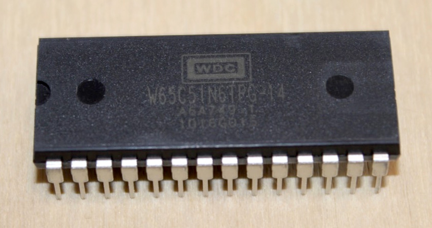 |
| MAX202CPE | RS-232 interface | 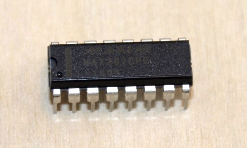 |
| 1.8342mhz oscillator | Oscillator for the buad rate generator | 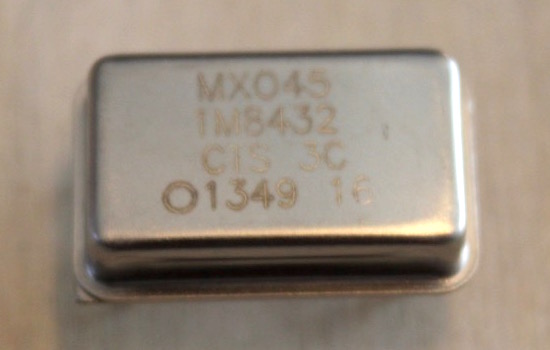 |
| DB9 connector | RS-232 connector | 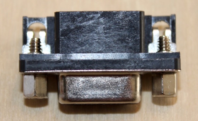 |
| 0.1uF Capacitors | Charge pump capacitors | 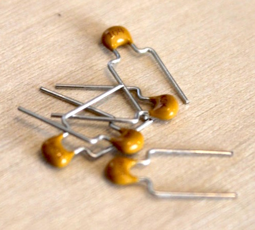 |