OLED
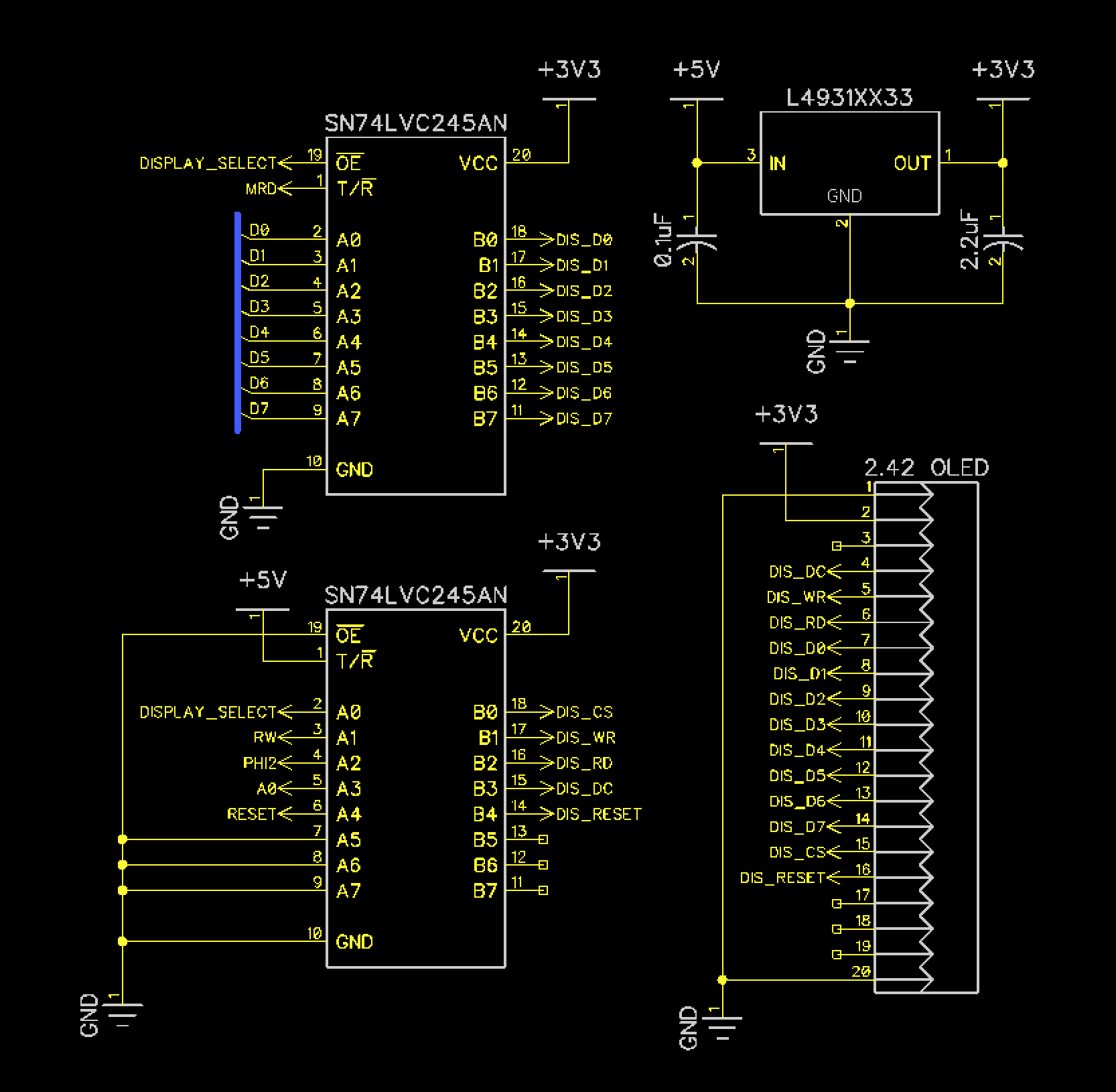
Circuit Diagram
Background
The OLED screen operates at 3.3v, so a voltage regulator and level shifters are needed to make the screen compatible with the rest of Dodo which runs at 5v. The screen supports a parallel bus mode which is ideal for interfacing with Dodo. The display also supports SPI and I2C, but the parallel interface is much faster. Over a serial connection several instructions would be needed per bit, rather than per byte. The screen i/o is mapped to memory. The video memory within the screen module is not directly accessible, it has to be written byte by byte using the commands listed in the datasheet for the screen controller (SSD1305). A 1k block of Dodo’s memory is reserved as a screen buffer.
All of Dodo’s 2D drawing APIs manipulate the video memory in system RAM. Once per game loop the video memory is copied to the screen.
Components
| Component | Description | Image |
|---|---|---|
| OLED Module | 128x64 pixel OLED | 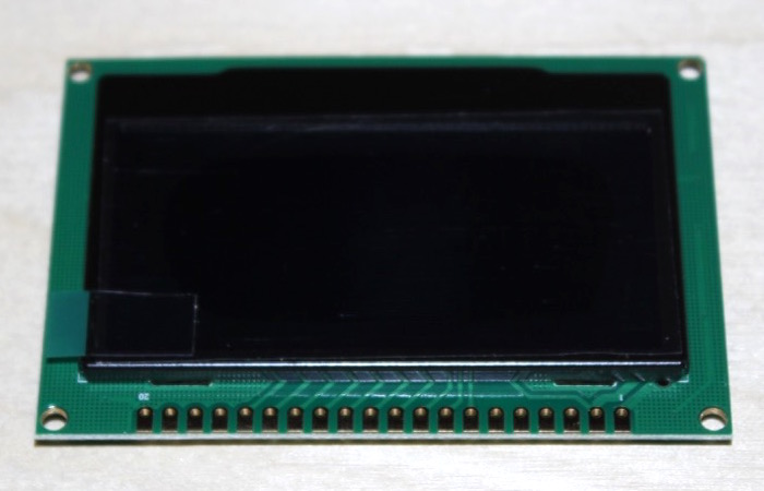 |
| 74LVC245 (2x) | 3.3v Level Shifters | 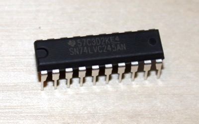 |
| L4931 | 3.3v Voltage Regulator | 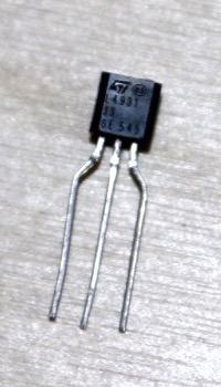 |
| 2.2uF Cap | Output Cap for Regulator | 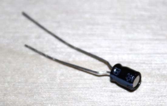 |
| 0.1uF Cap | Input Cap for Regulator | 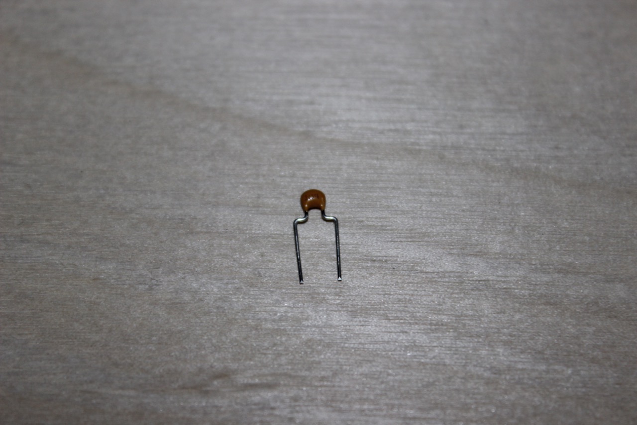 |
| Hardware | Screws, Spacer, and Nuts for Screen | 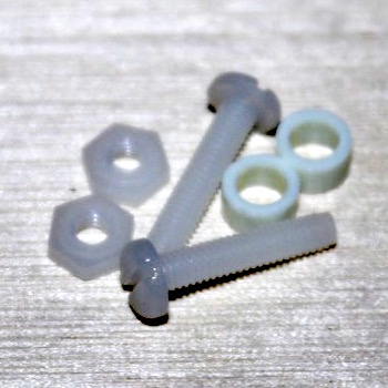 |
| Connector | 20 Pin Connector for Screen | 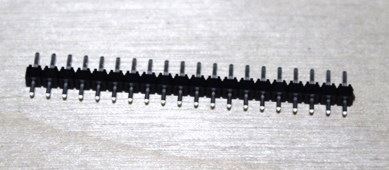 |