Buttons
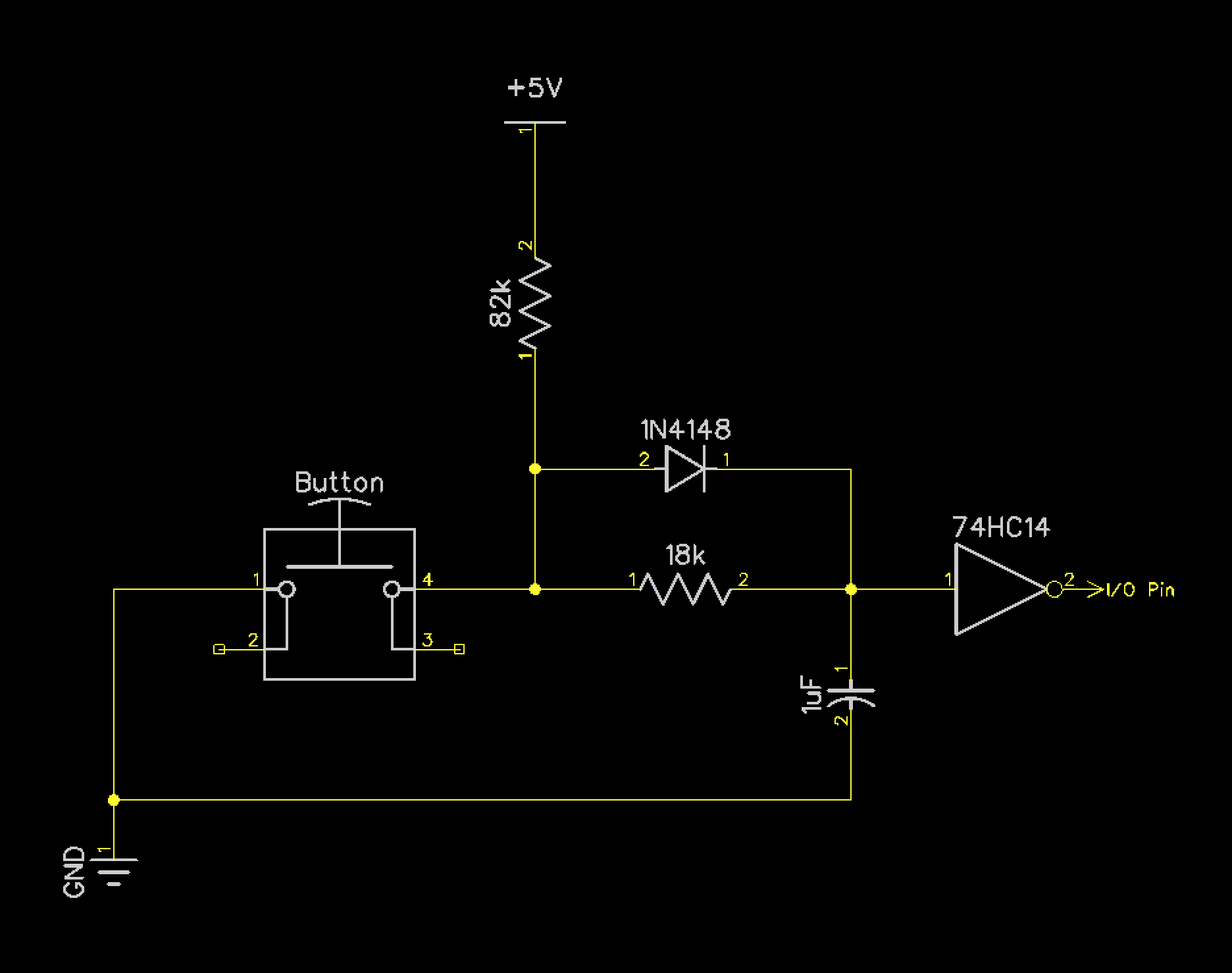
Circuit Diagram
Background
When a button is opened or closed, for a short time period the signal erratically bounces up and down as it settles toward +5v or 0v. In this period, reading the state of the pin may return the wrong value which could manifest itself as two button presses instead of one, or a missed button press. In order to clean the signal to accurately read correct values, the button needs to be “debounced.” This debounce circuit is an RC Debouncer as described here. Read part 1 as well for a more thorough description of the debouncing problem.
There are a total of 6 game buttons in Dodo and each is connected to an I/O pin of Port A of the 65C22S. The above debounce circuit is replicated 6 times on the circuit board. Luckily, the 74HC14 just happens to contain 6 inverters.
Components
| Component | Description | Image |
|---|---|---|
| Pushbutton and Cap (6x) | Game Buttons | 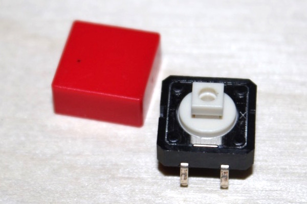 |
| 18k Resistor (6x) | Part of RC Debounce Circuit | 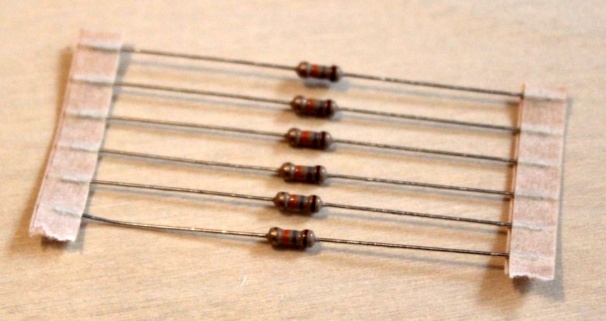 |
| 82k Resistor (6x) | Part of RC Debounce Circuit | 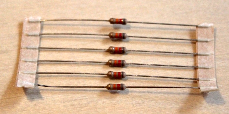 |
| 1 uF Cap (6x) | Part of RC Debounce Circuit | 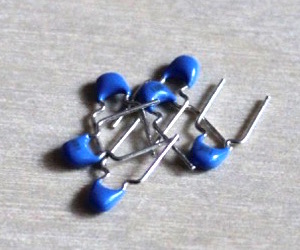 |
| 1N4148 (6x) | Diode | 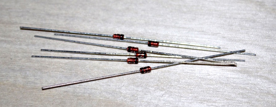 |
| 74HC14 | Hex Inverting Schmitt Trigger | 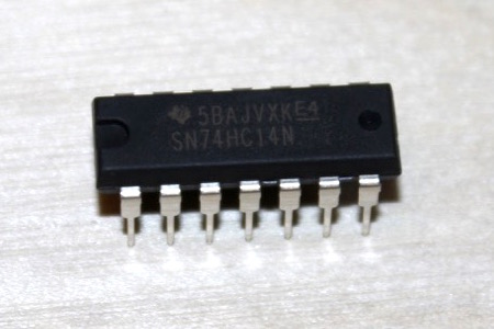 |