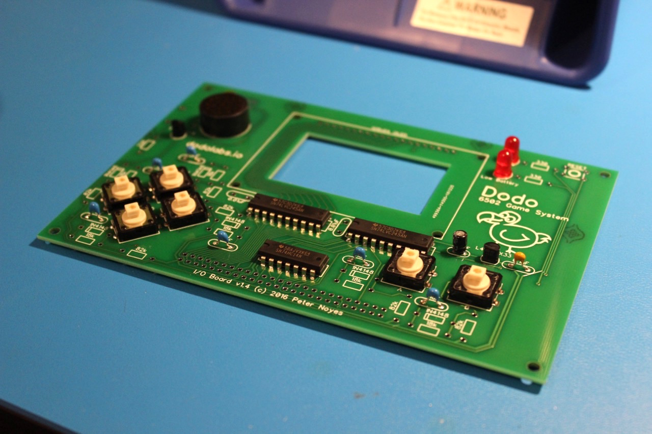
Assembly
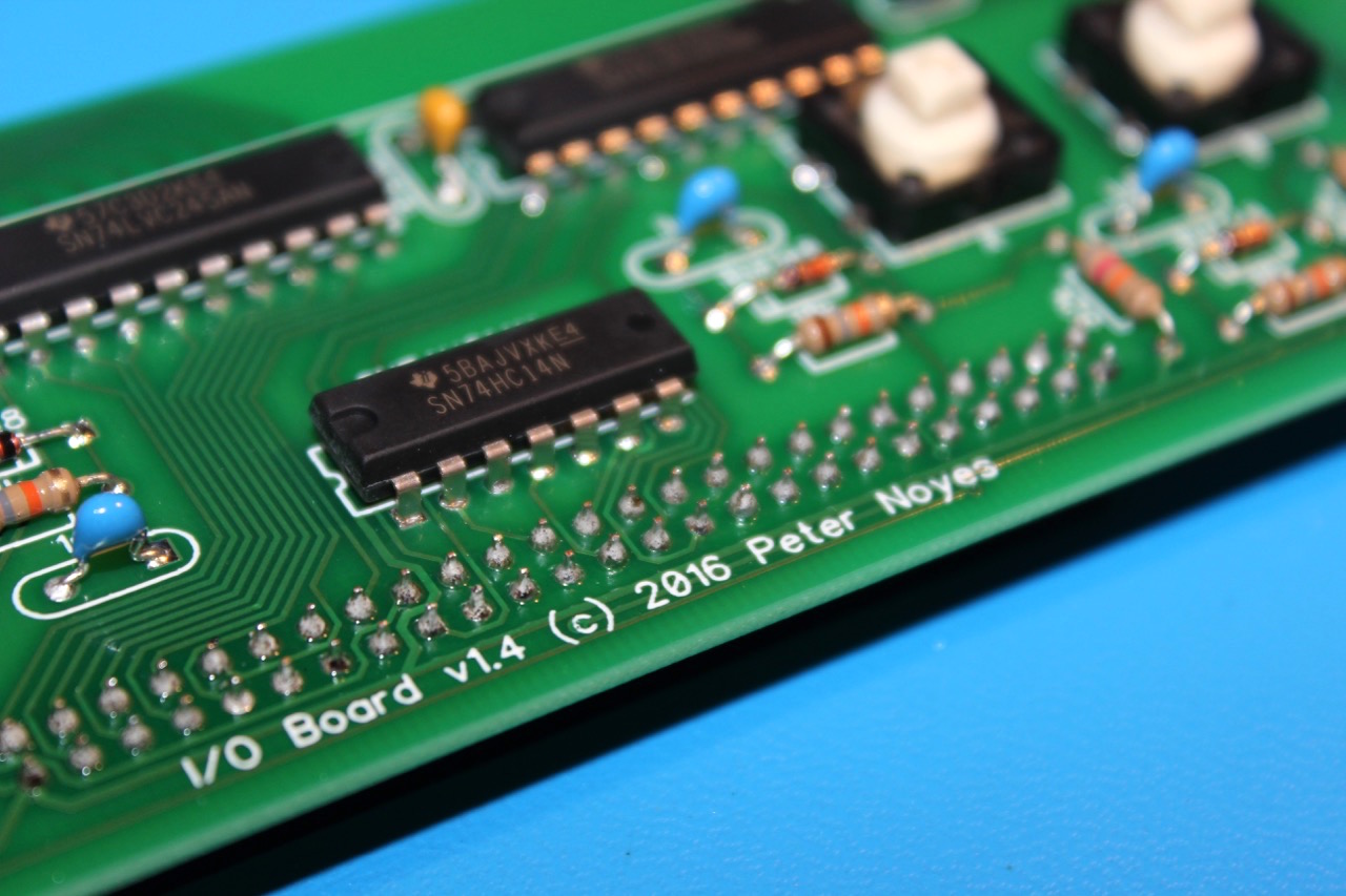
Step 1 - ICs
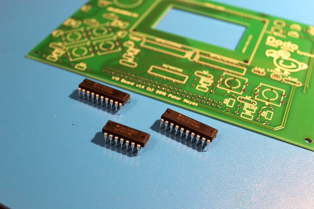
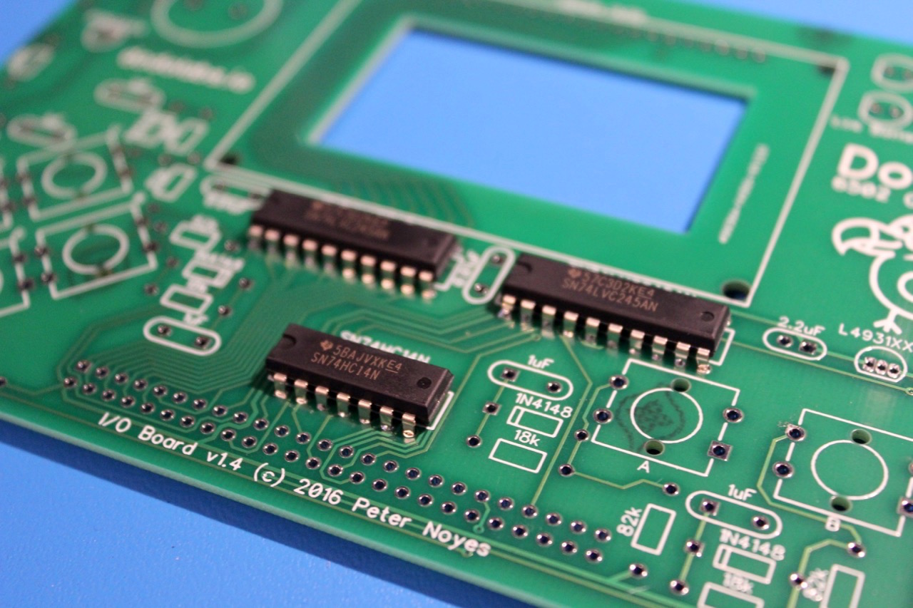
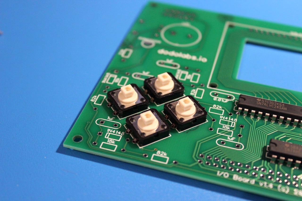
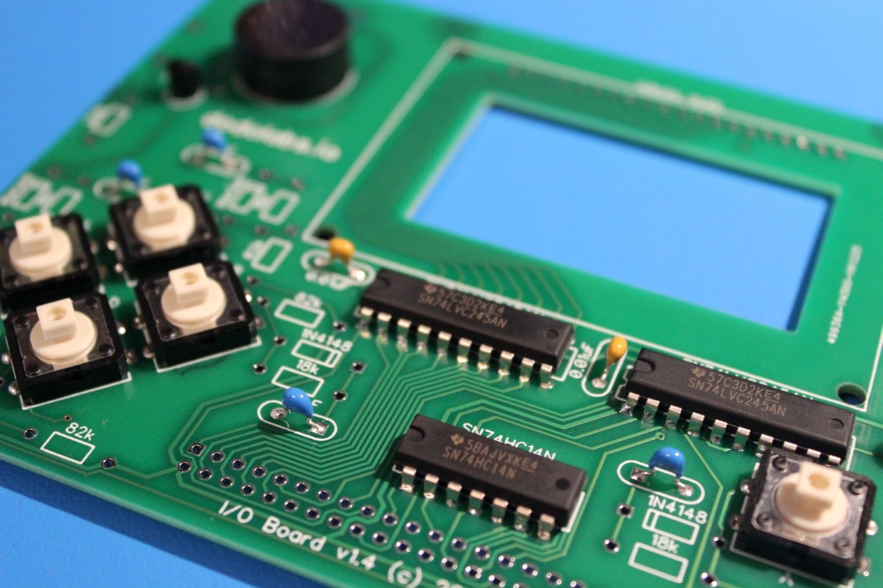
There are 3 ICs on the I/O board. Two level shifters for the Display, and a Schmitt Trigger Hex Inverter that helps get clean button press signals. As with the main board it is easiest to install the ICs first. Again, be sure that the orientation of the chips are correct.
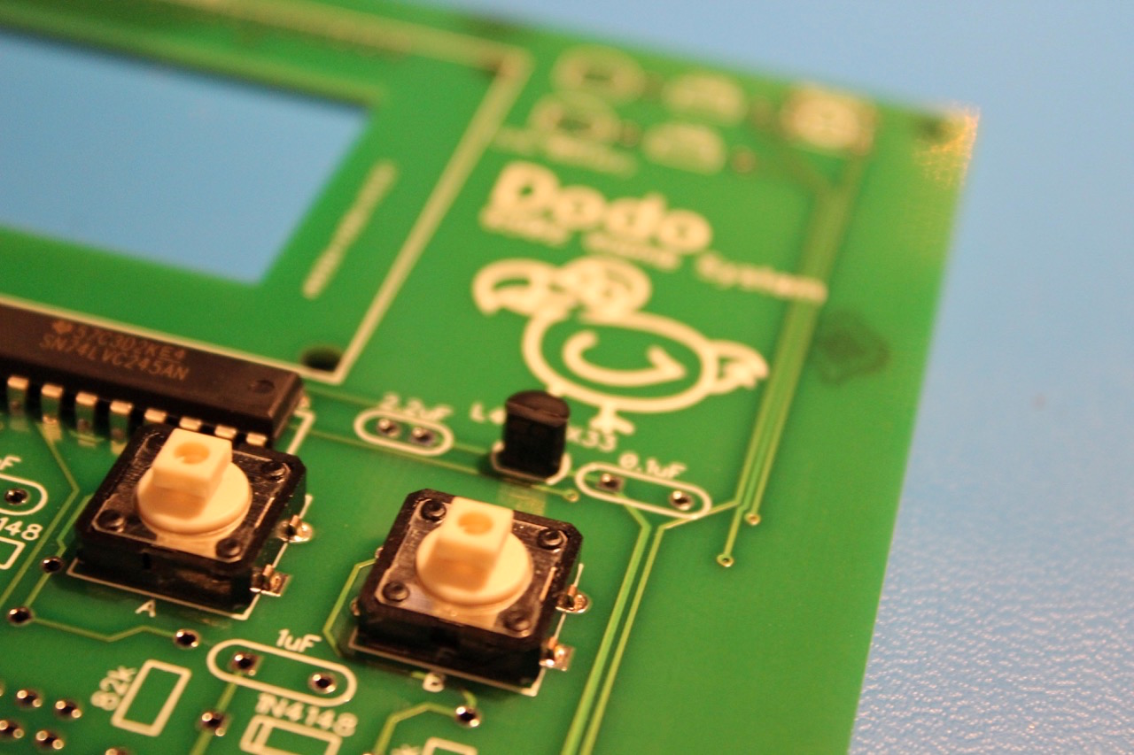
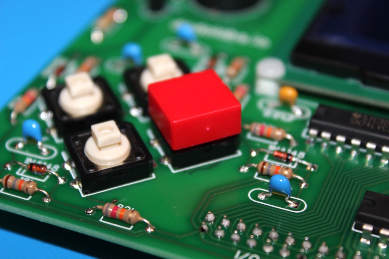
Step 2 - Buttons
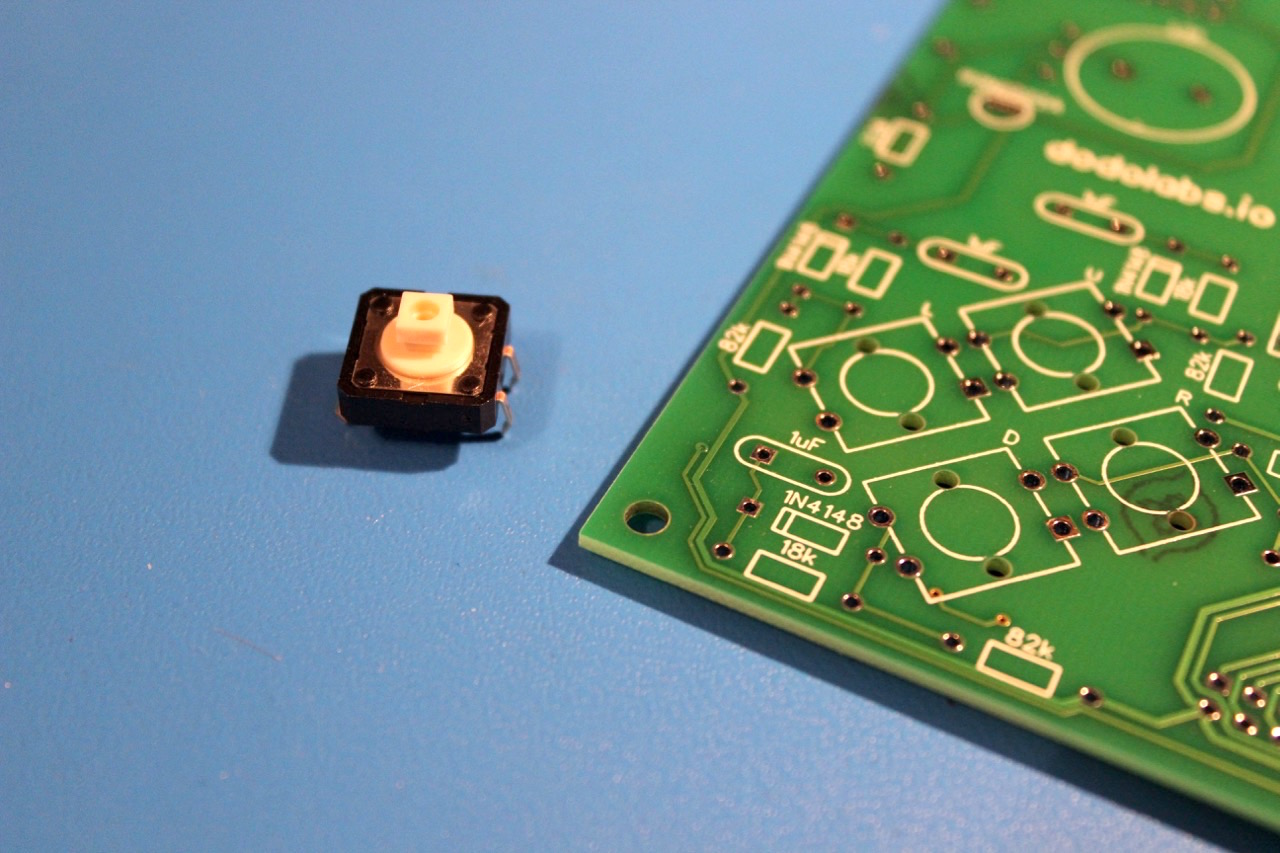
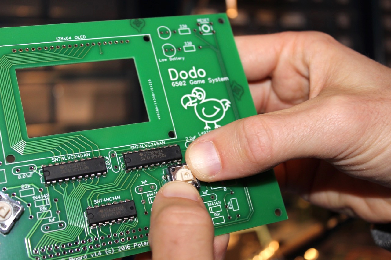
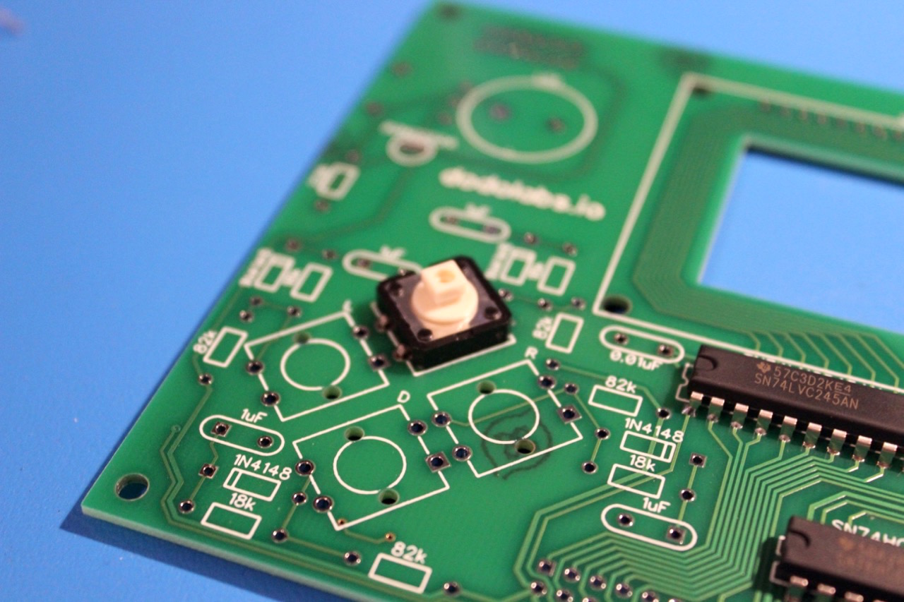
There are 6 buttons that need to be installed. They require a good amount of force. The best way is to apply pressure using both thumbs on opposite corners of the button. Apply even pressure and be careful not to let any pins bend under the button. There are two plastic pins on each button that also go through holes. Wait to install the button caps.
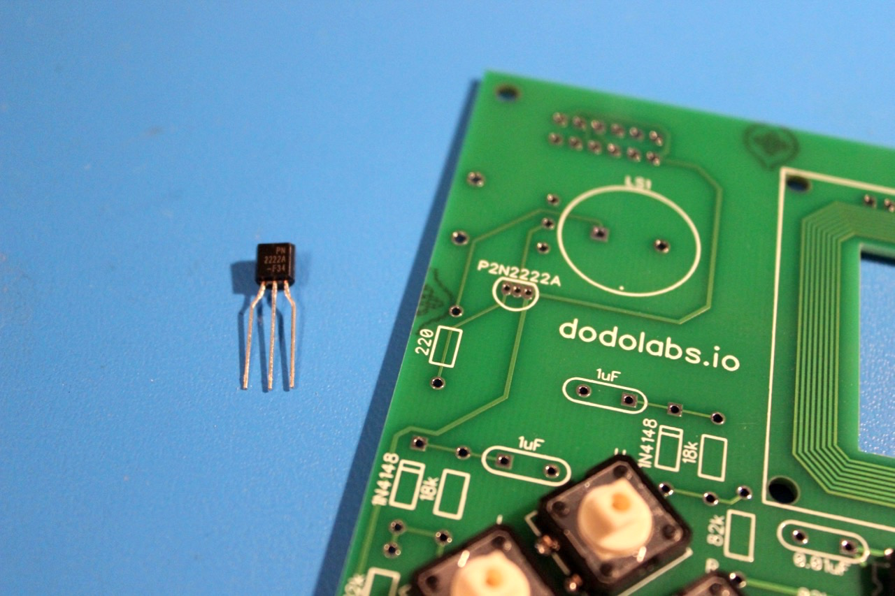
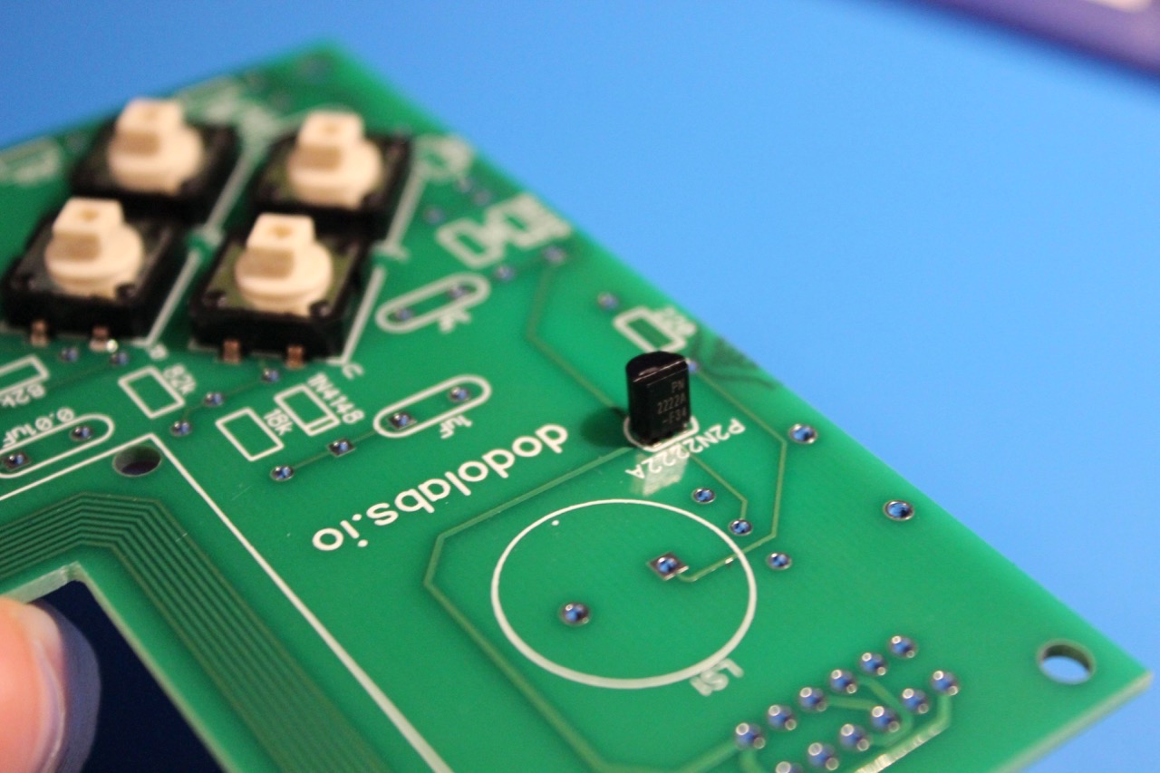
Step 3 - P2N2222A
The P2N2222A is another component in the TO-92 package. Be sure to not mix it up with any of other 3 and to match the silk screen on the pcb for the orientatio.
Step 4 - L4931
As with the transistor above, be careful that the correct component is used and that the orientation is correct.
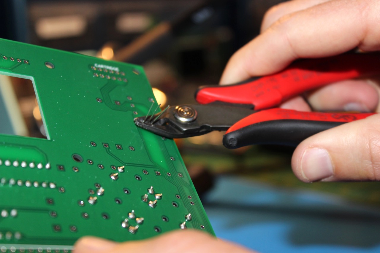
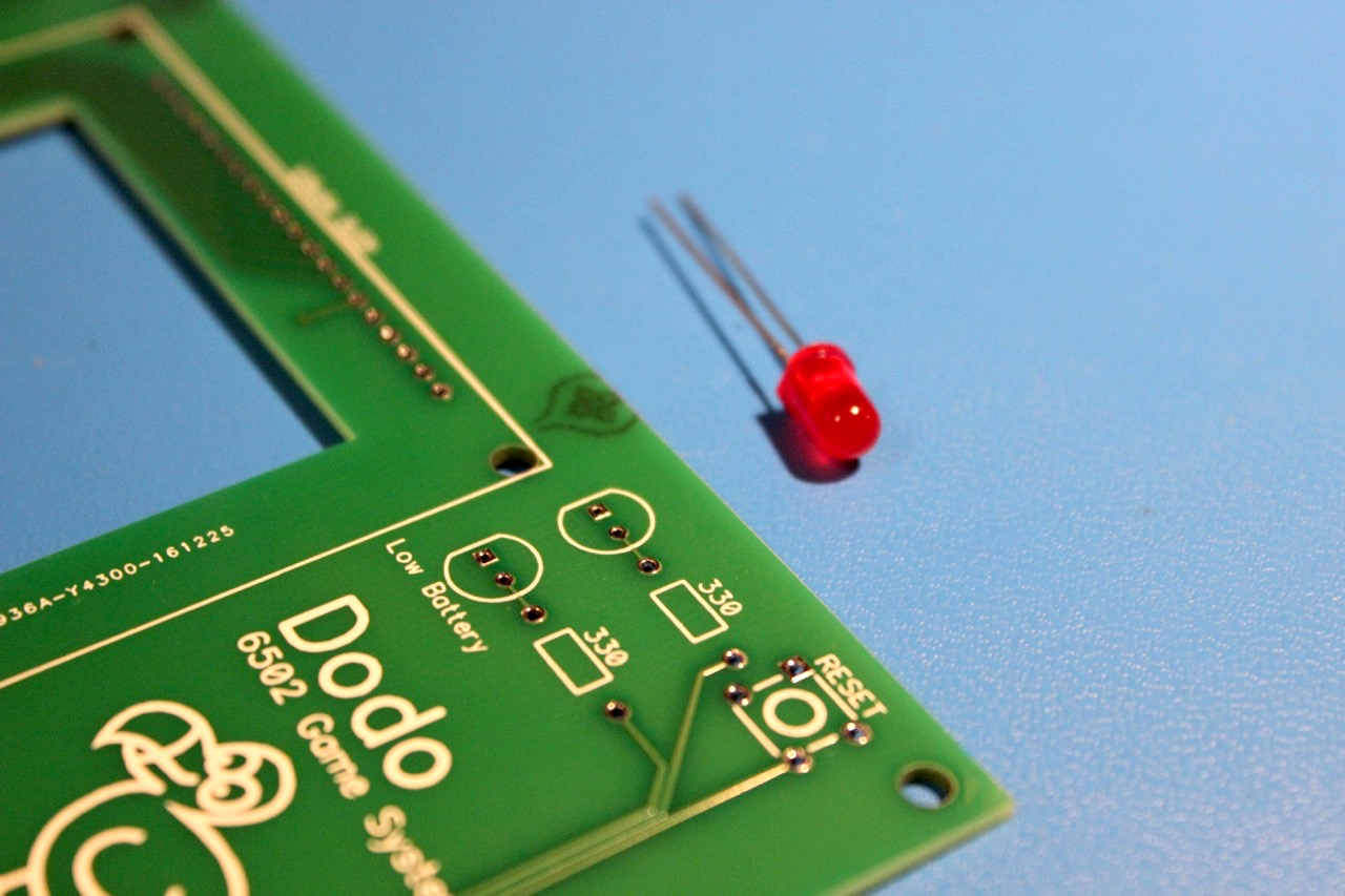
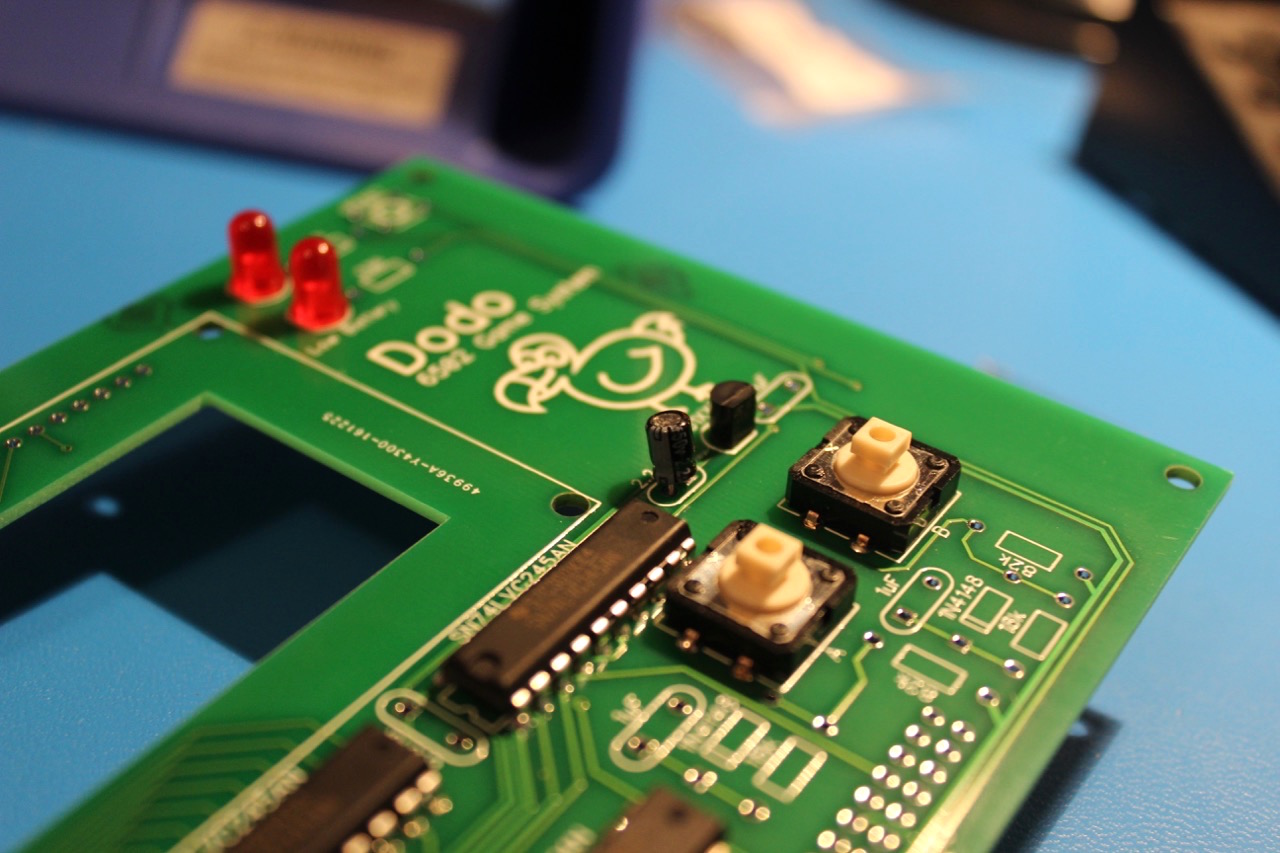
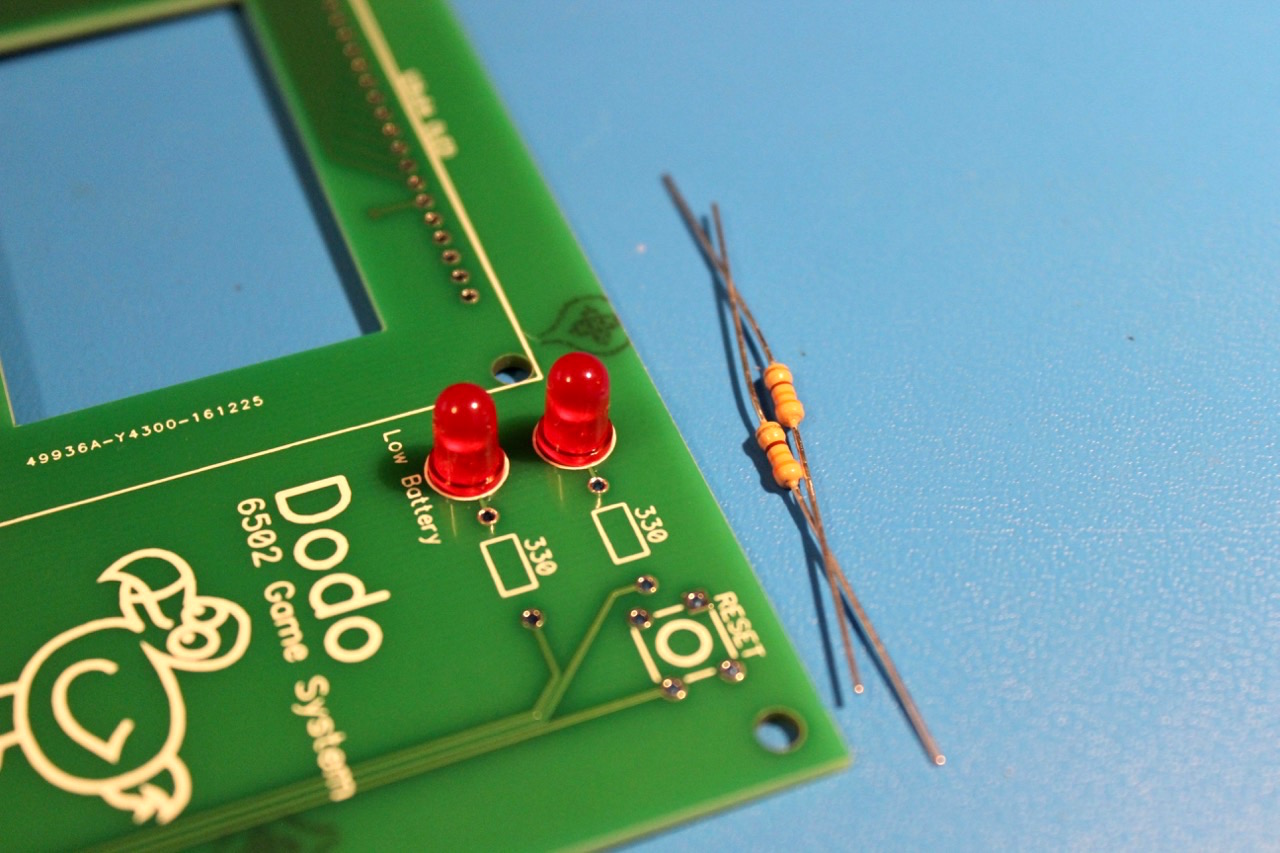
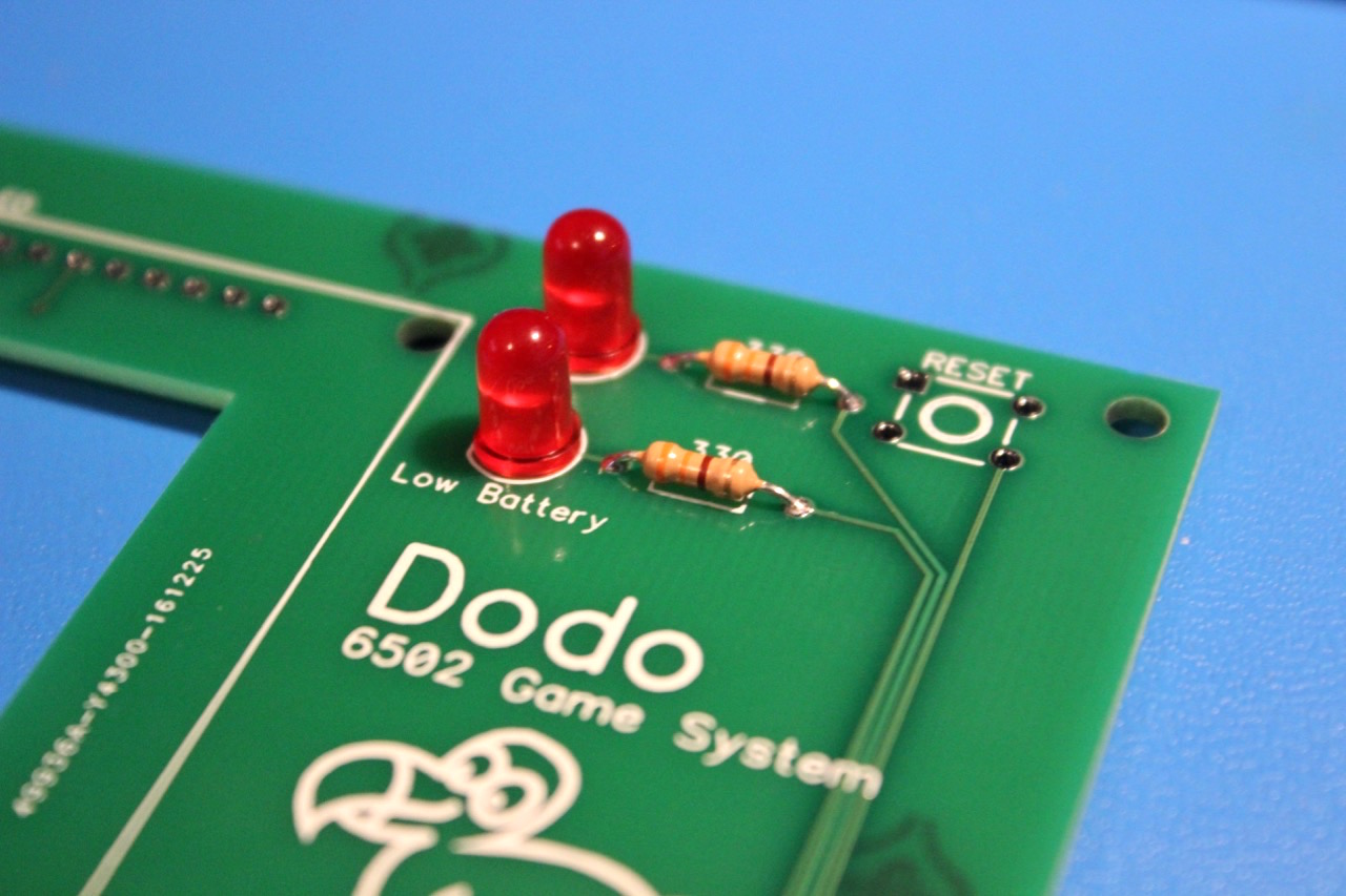
Step 5 - LEDs
The LEDs are polarized. There is a flat side of the LED that needs to match the flat side of the silk screen. Trim the leads after soldering.
Step 6 - Voltage Regulator Capacitors
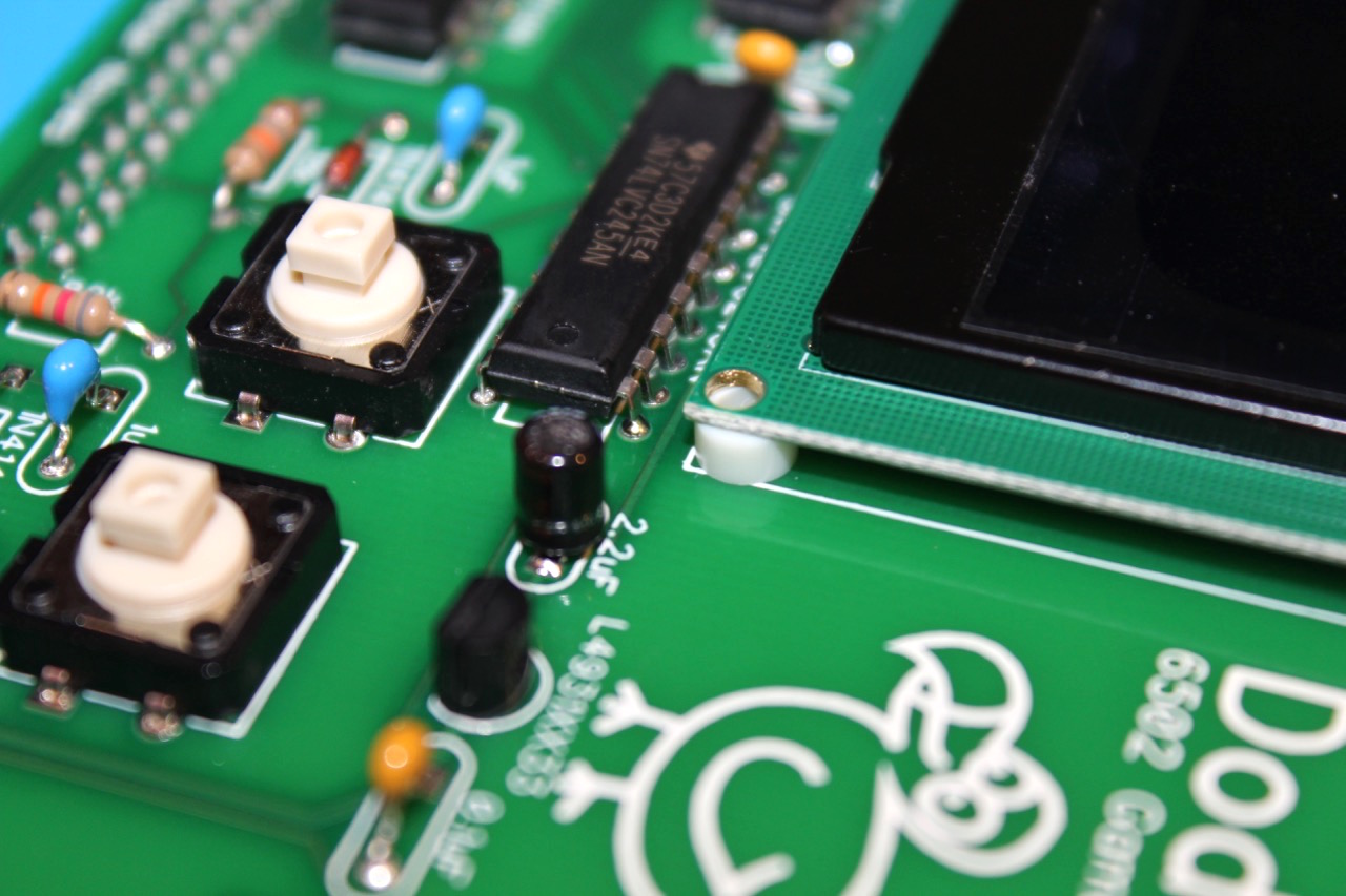
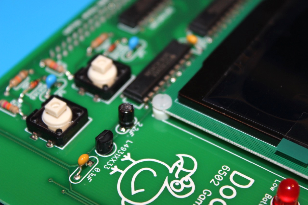
The 2.2uF capacitor is polarized. Match the picture below. The positive lead goes into the hole which has 2 traces on the top side of the PCB connected to it. The negative side connects to the ground plane on the underside of the board. The negative lead of the capacitor is marked with the stripe.
The other capacitor is not polarized. Trim the leads of both capacitors after soldering.
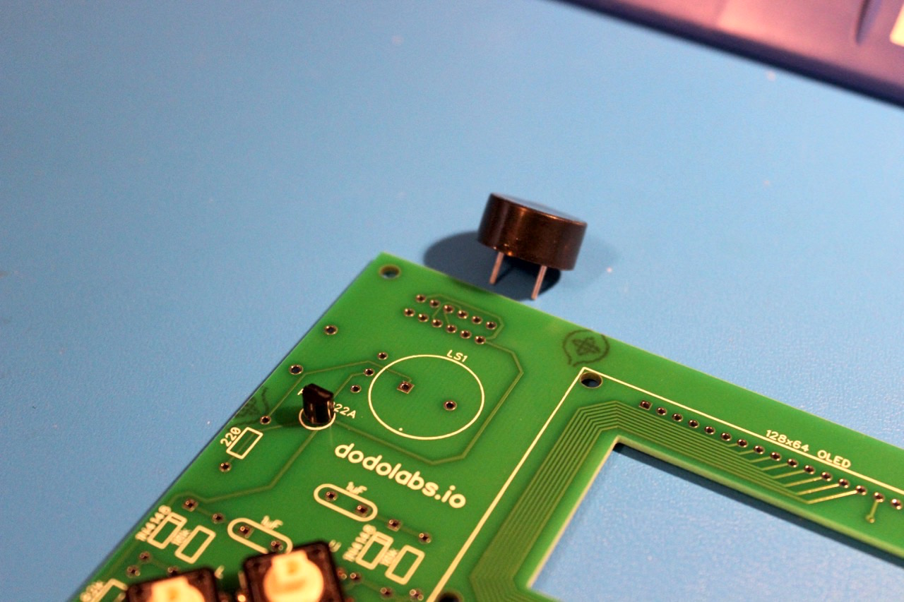
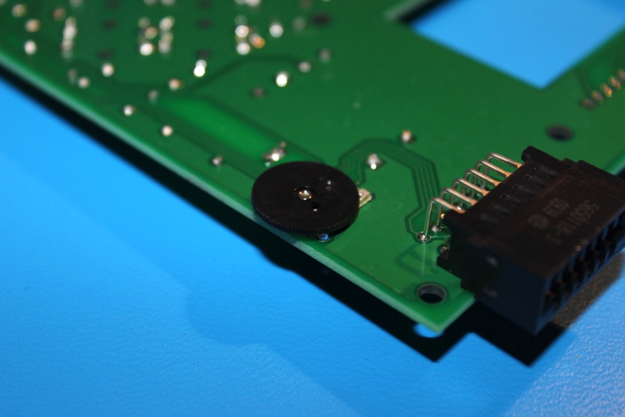
Step 7 - Speaker
The speaker is polarized. There is a dot on the PCB that needs to match a dot on the speaker. See the picture below. Trim the leads after soldering.
Step 8 - Reset Button
There is no picture of the Reset button, but installation should be straight forward.
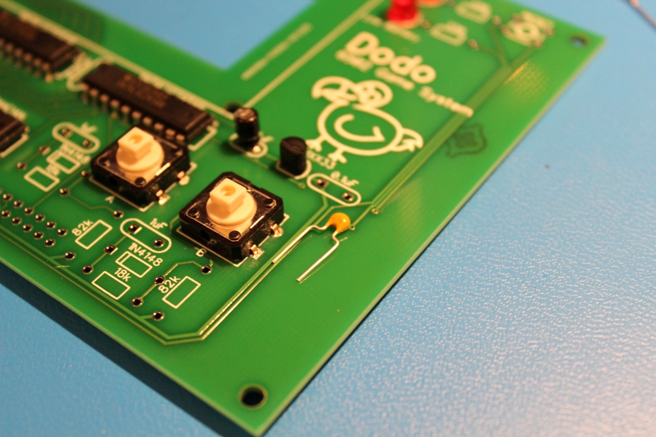
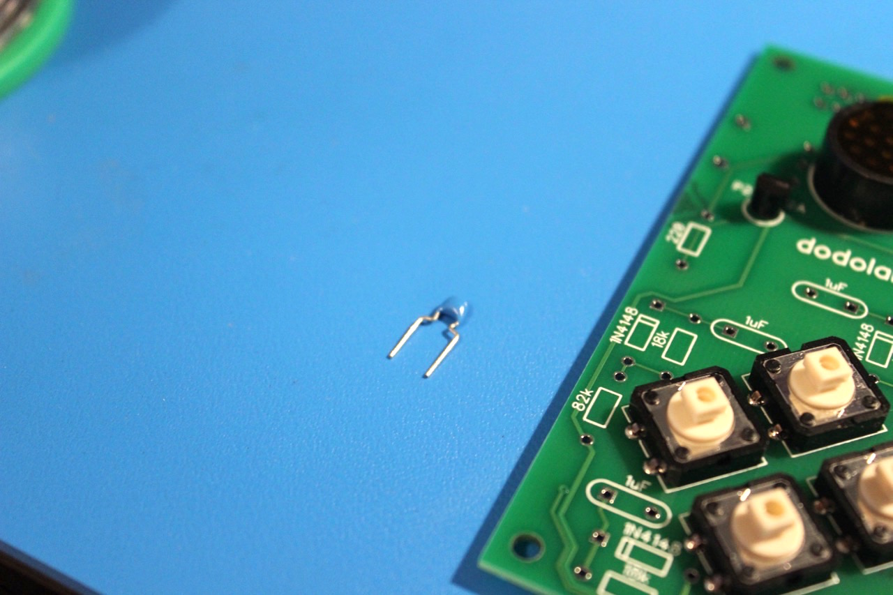
Step 9 - Button Capacitors
There are 6 1uF button capacitors. These capacitors are not polarized. Trim the leads after soldering.
Step 10 - IC Bypass Capacitors
There are two 0.01uF bypass capacitors (marked with a 103) for the level shifters. These capacitors are not polarized. Trim the leads after soldering.
Step 11 - 330 Ohm LED resistors
The 330 ohm resistors are ORANGE ORANGE BROWN
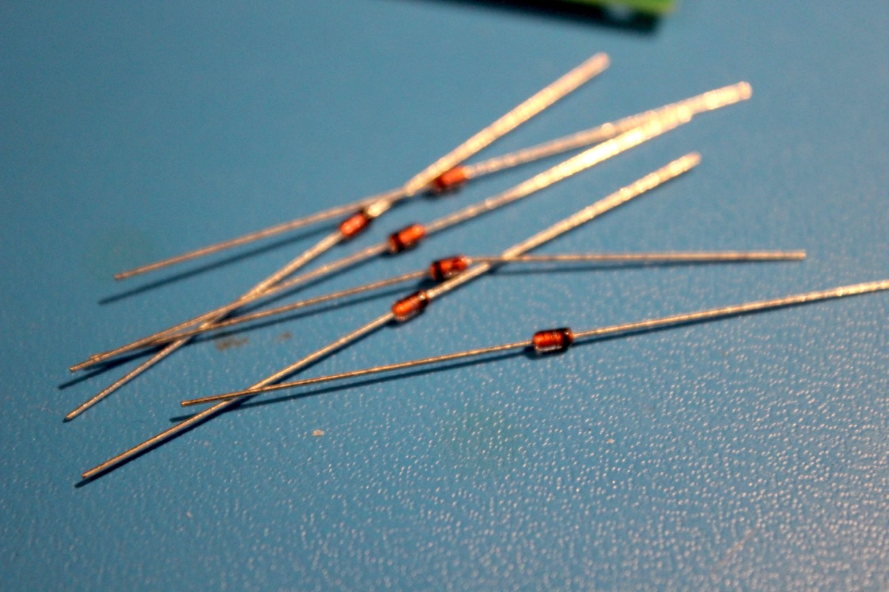
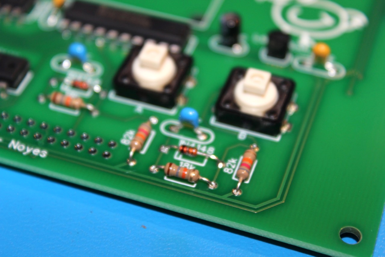
Step 12 - Diodes
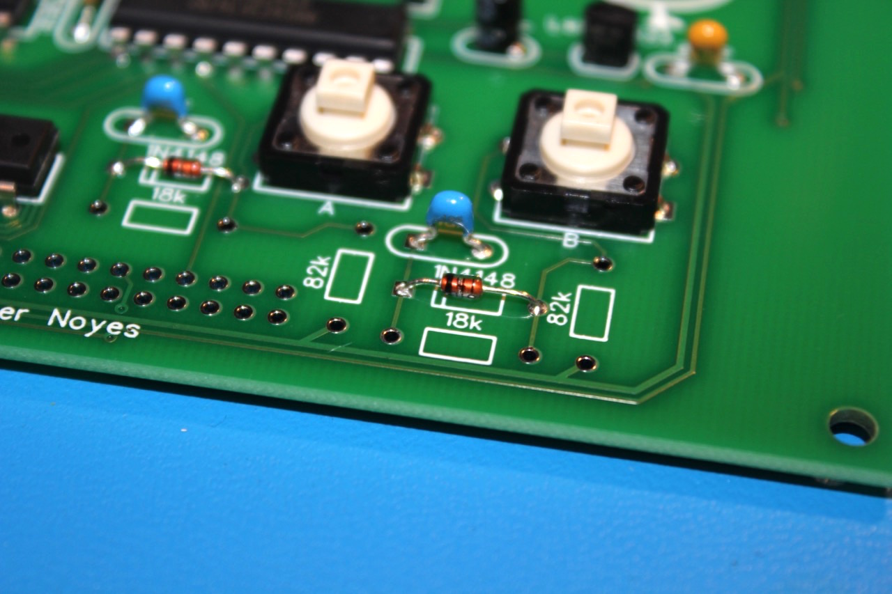
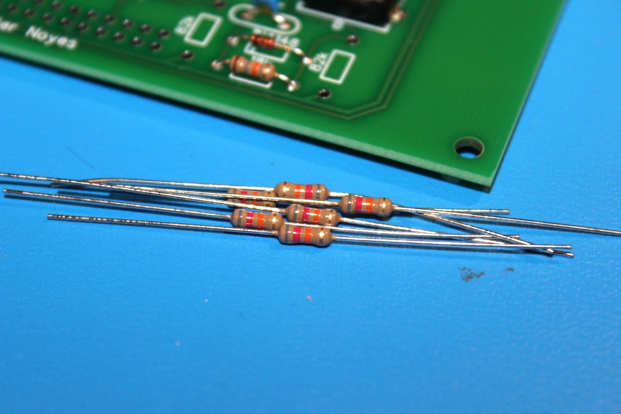
Step 13 - 18k Resistors
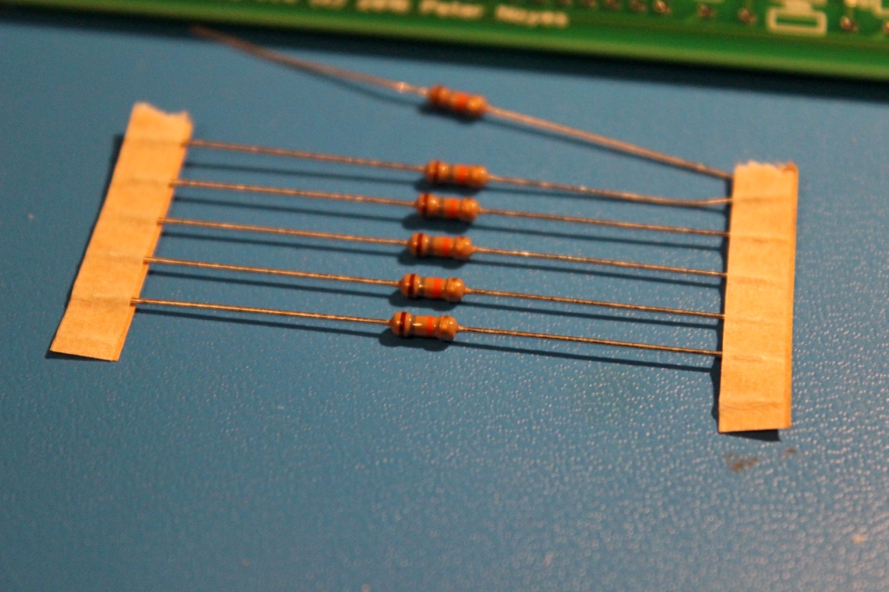
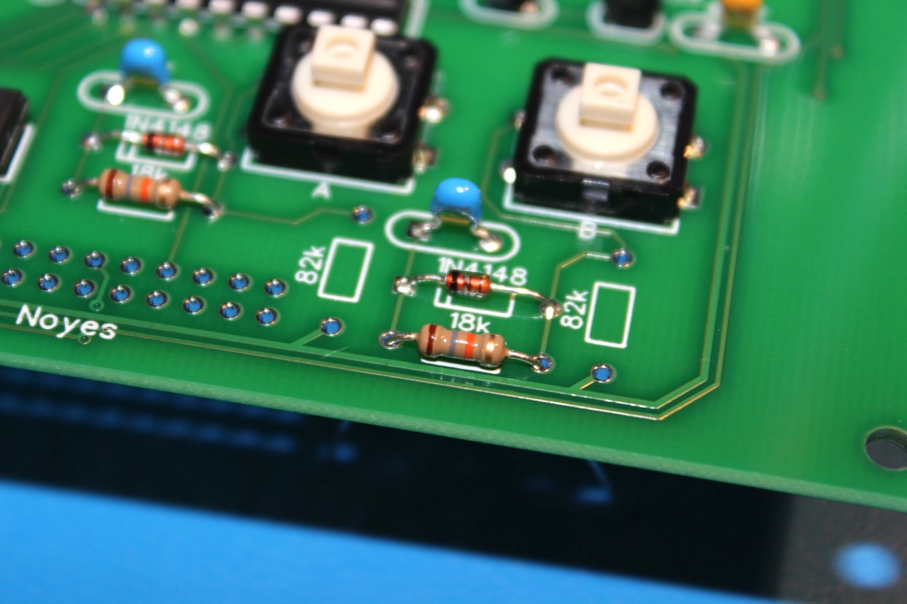
Step 14 - 82k Resistors
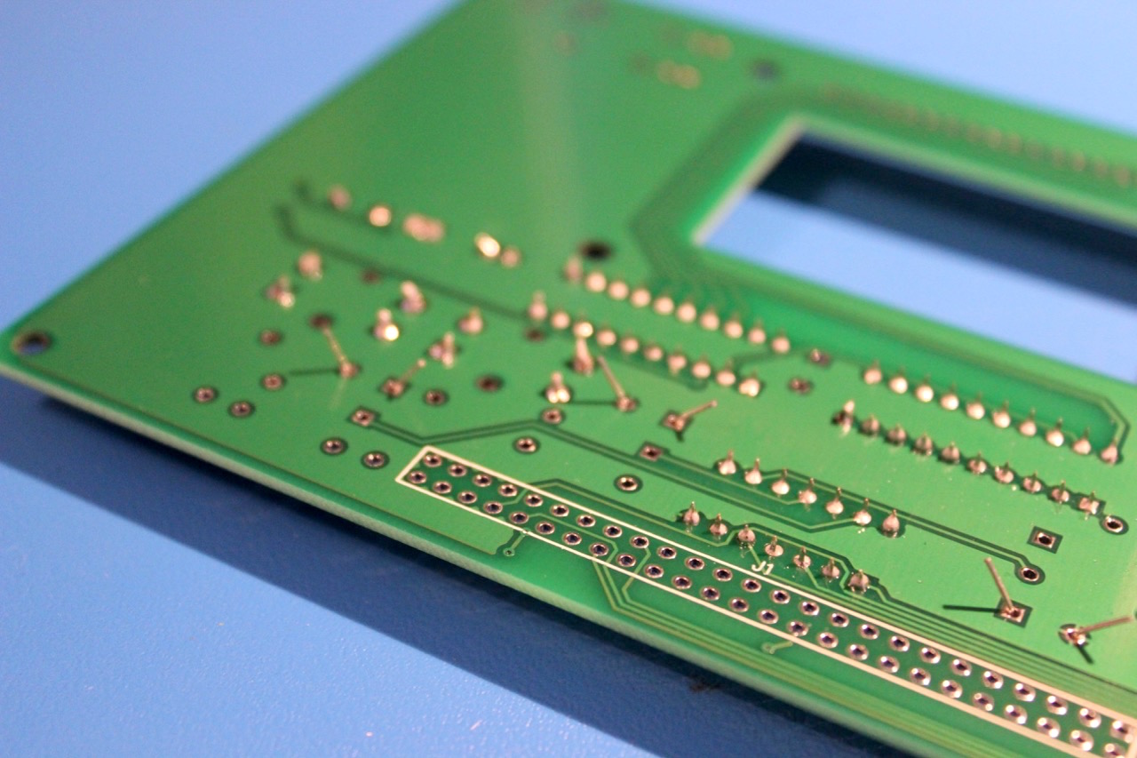
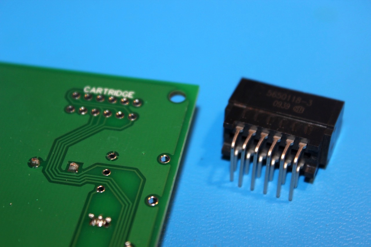
Step 15 - Main Board Header
The main board header is installed on the backside of the board so that it will mate with the opposite header on the main pcb.
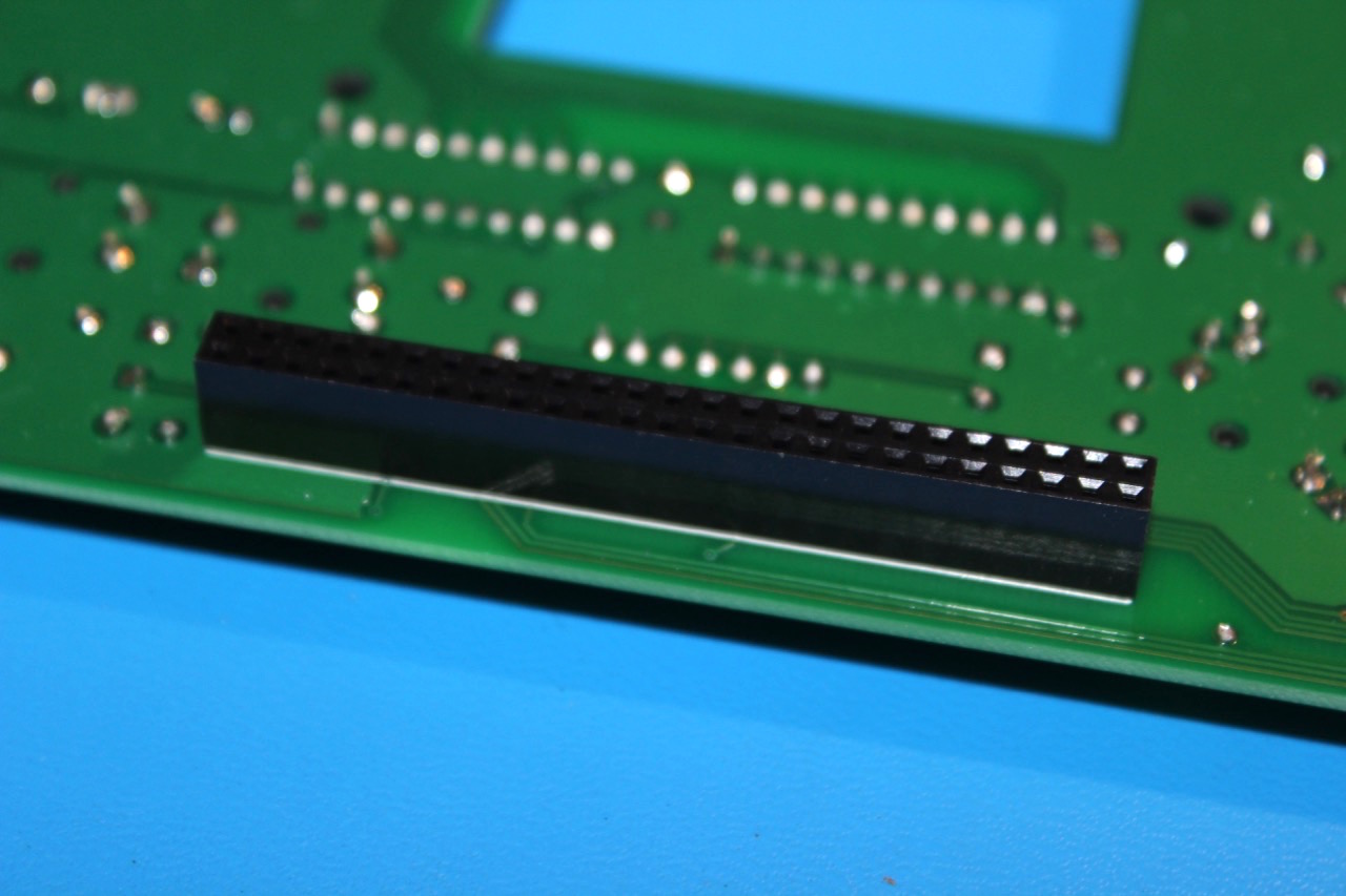
Step 16 - Edge Connector
The edge connector is also installed on the backside of the board. There is a small plastic lip that should go directly up against the side of the PCB.
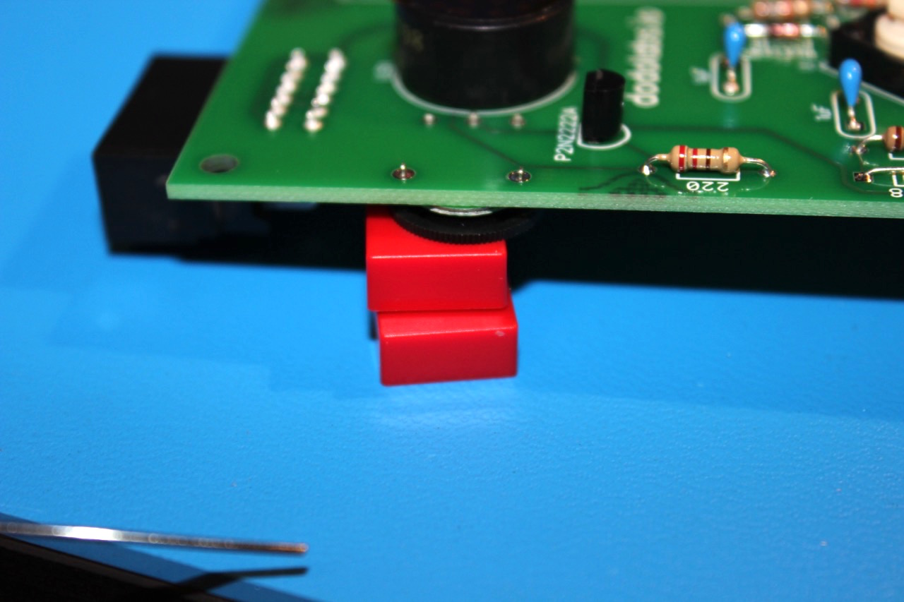
Step 17 - Potentiometer & 220 Ohm Resistor
The potentiometer is also installed on the underside of tbe board. A stack of button caps can be used to help hold it in place for soldering.
The 220 ohm resistor is RED RED BROWN
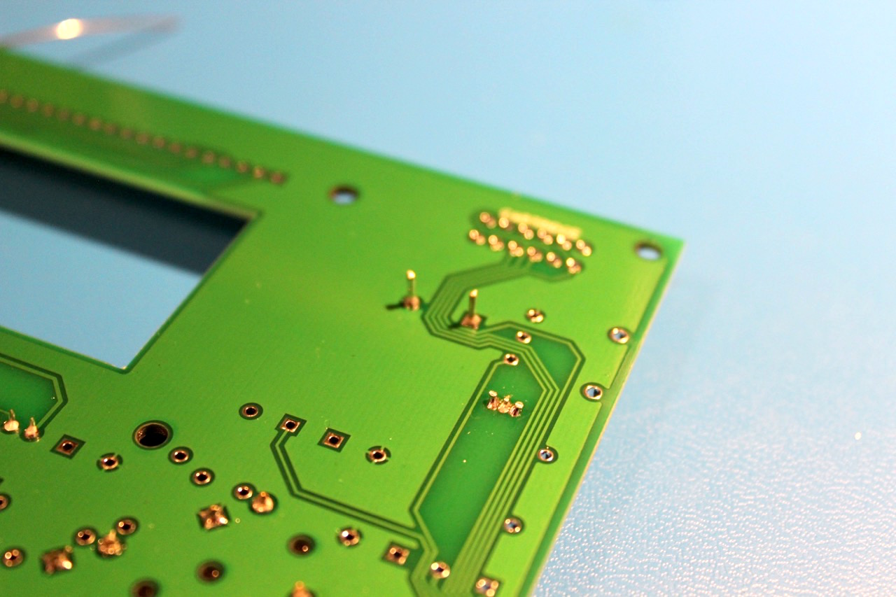
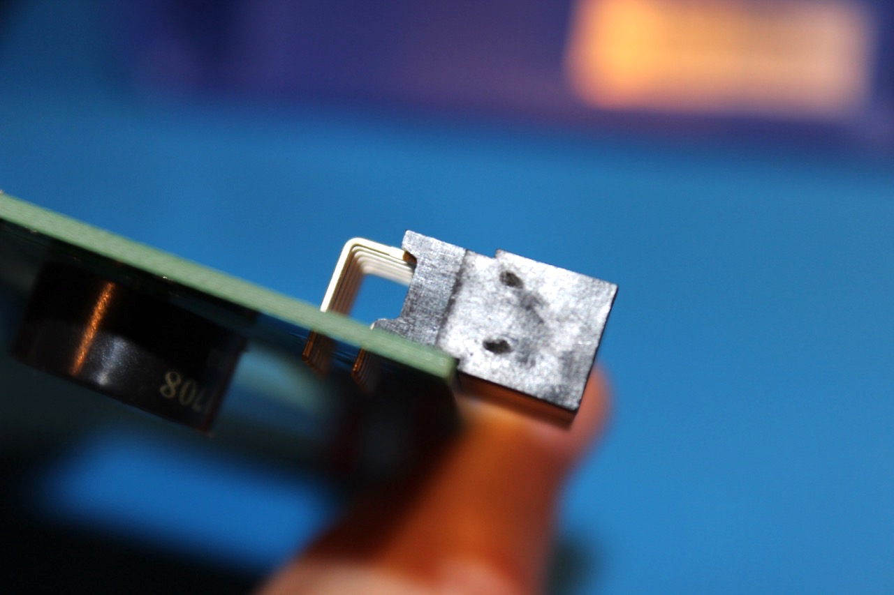
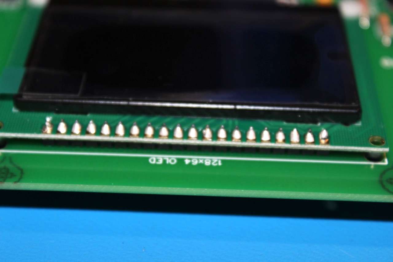
Step 18 - Screen
The basic idea for installing the screen is to first secure it in place with the screws and then solder it in place. There is a 20 pin double sided header that connects the screen assembly to the PCB. There are two sets of nylon screws, spacer and nuts. The screws should go in the bottom 2 holes of the screen. No screws are needed in the top because the soldered header secures the screen. Do not remove the protective sticker from the screen until the board is completely soldered.
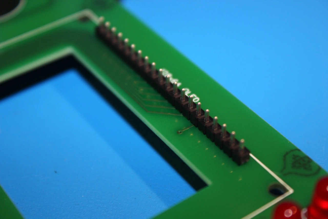
Place the header in the PCB, with the longer pins going into the board.
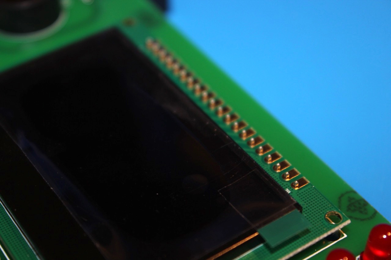
Place the screen with the pins going through the assembly.
Place the spacers in place between the board and the screen over the bottom holes.
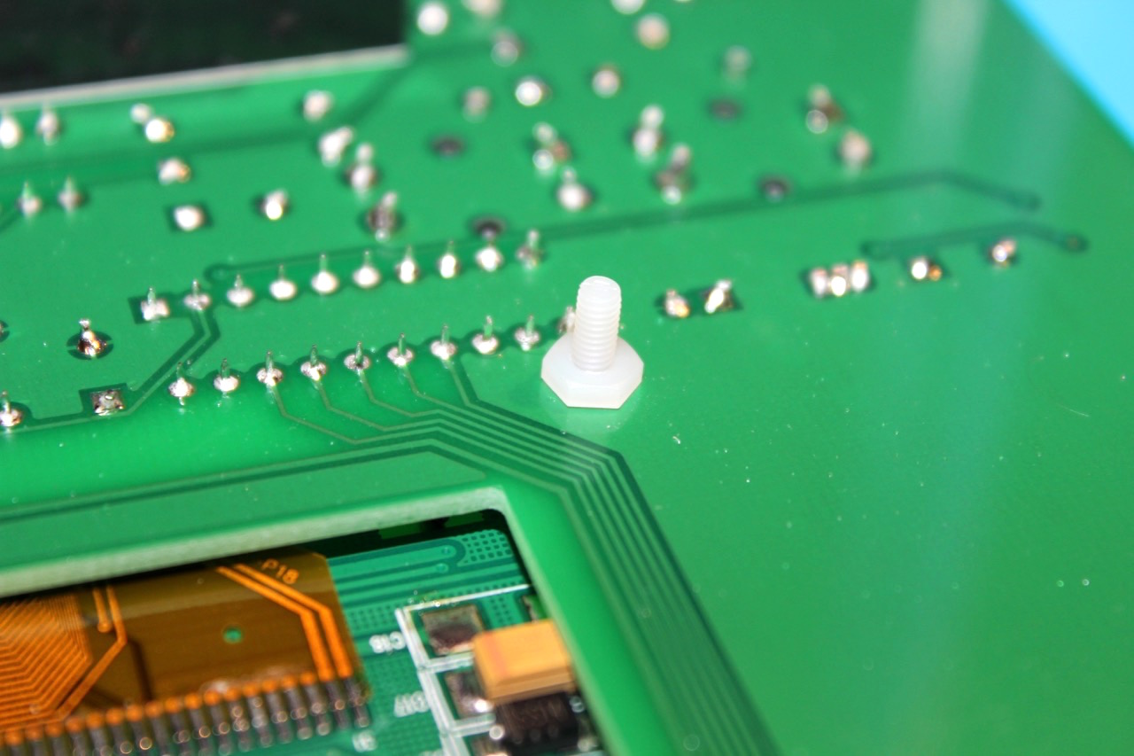
Install the screws and nuts hand tightening until secure.
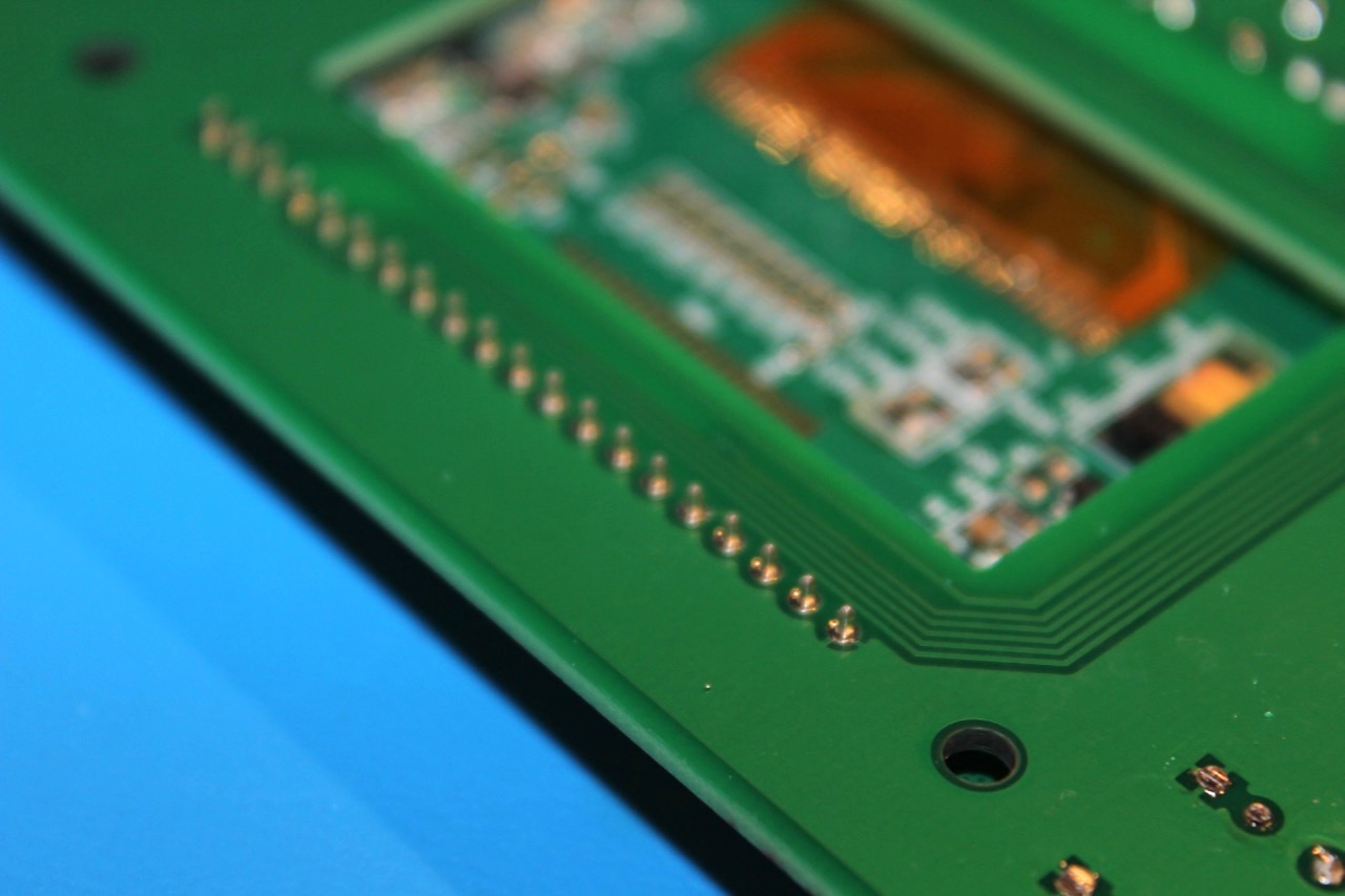
Solder the header on underside of the PCB.
Solder the screen on top.
Step 19 - Button Caps
Install the 6 button caps by firmly pressing the caps straight down onto the buttons.
Step 20 - Testing
At this point, the board can be powered up for the first time. Do the following:
- Install Batteries
- Install Game Cartridge (Either direction will work)
- Plug the I/O board into the main board. Be very careful that the headers are aligned. It is easy to accidently be off by a pin or even an entire row. The board doesn’t need to be fully inserted for the initial test.
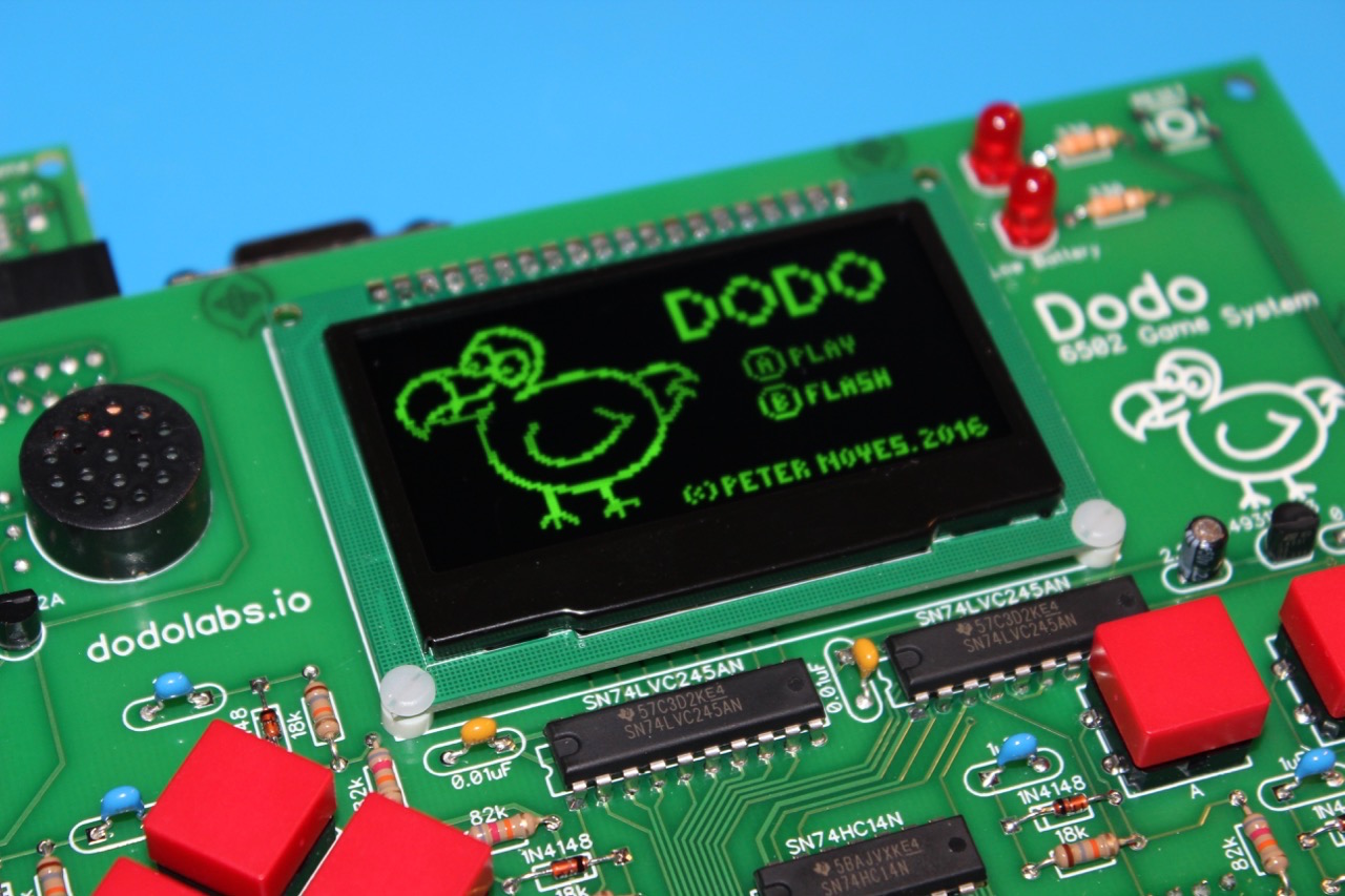
Power on Dodo using the switch. Ideally the splash screen shows up! If not check the following:
- Check to that all pins are soldered (common problem)
- Make sure the connection to between the boards is correct
At this point if your Dodo still is not working e-mail hello@dodolabs.io for further assistance