Warnings
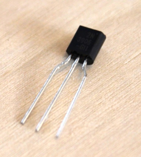
- There are 4 distinct components in the TO-92 package that look nearly identical. Be very careful to install these in the correct locations, they are tough to desolder.
- The IC socket is intended for the EEPROM in case it ever needs to be pulled for reprogramming.
- The electolytic capacitors are polarized. Be careful that they are installed with the correct orientation.
- It can be tricky to install the larger ICs, gently bend the pins inward so that they can be inserted into the holes on the PCB.
- Refer to the silk screen on the PCBs for correct orientation. Not all chips are orientated the same direction.
- The 0.01uF and 0.1uF capacitors may look nearly identical. They are distingushed by tiny writing of 103 for 0.01uF and 104 for 0.1uF.
- The battery holders can also be tricky to solder. The leads need to first be trimmed. A helping hands tool is very useful for holding everything in place. Without a helping hands, finding something thin to place under the PCB so that it is just tall enough to have the battery holders rest in place. Be sure the polarity of the battery holders match the polarity shown on the PCB. Also, use a decent amount of solder to hold them in place.
- There are two unpopulated components on the PCB; RESET and 5V. The main board of Dodo is designed to work as a generic single board computer without the game based I/O board. A reset butotn on the main board would be useful in the case that it is used by by stand alone. For this kit the reset button should be installed on the I/O board and should be left unpopulated on the main board.